Ubidium is an entirely self-contained unit, with all the required components accessible directly on the exterior of the shell. The system is designed to ensure all components are protected from water ingress / damage, and does not require any additional cover or lid.
The system is primarily constructed from a highly durable PLASTIC TYPE, designed to withstand the, sometimes, harsh conditions of sports events.


The base of the system features recessed text "THIS SIDE DOWN" and the system should always be setup accordingly to prevent water ingress. Additionally on the base are 4 mounting screw holes for permanent installations, if mounting to a wall then this should be done with the front side facing down.
Ubidium contains an active ventilation system which will be triggered in hot temperatures or in high humidity environments to prevent the formation of condensation on sensitive components.
A handle on the left side can be used to carry the system.
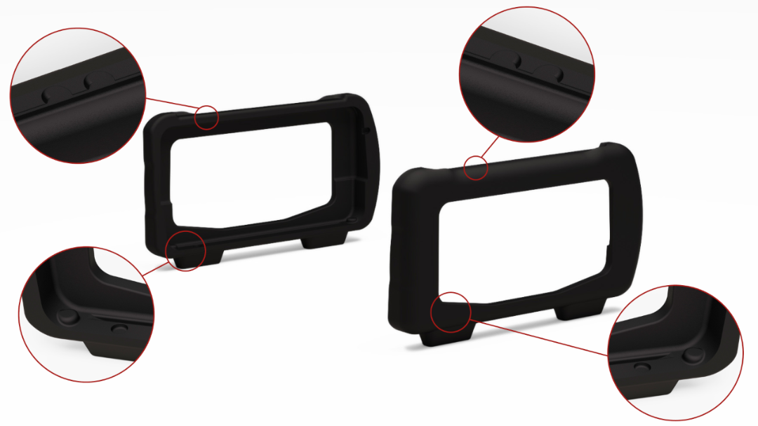
Bumpers
Two rubber bumpers provide additional drop / fall protection to Ubidium, these also elevate the system from the ground with the feet on the bottom side.
The rubber bumpers are additionally designed with a curved profile on the back side to prevent Ubidium from being stood with the Water Resistant Flap facing upwards.
When removing / installing the rubber bumpers it is important to ensure the correct orientation is used. The left and right bumpers must be installed accordingly, this can be identified by the cutouts towards the front side both top and bottom.
Battery Compartments
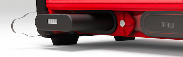
The front side of the system contains two battery compartments for installing supported battery units.
Each compartment is covered by a transparent Polycarbonate cover, this ensures the current battery status can always be seen visually without opening the system. Each compartment is also sealed with a foam pad around the edge of the opening, this creates a seal with the compartment flap.
To unlock the compartments turn the center locking knob either clockwise or anti-clockwise to align the cut-out edge with the compartment you wish to open.
Batteries must be entered in the correct orientation, aligning the cutout ridge with the notch in the top side.
The batteries can safely be removed at any time.
Display
Ubidium contains a 6.2" integrated backlit display designed to be readable in any conditions when switched on.
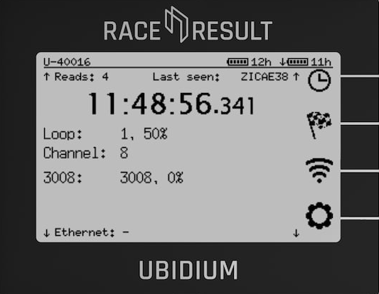
The display is protected by a high-impact thermally tempered glass, additionally the ridges above and below the screen prevent large objects from crushing the screen.
The display is designed to be readable whilst standing over the device normally.
Keypad
The keypad of Ubidium is completely sealed inside the top case of the system, rubber keys cover the tactile switches below making the buttons easy to use in all conditions.
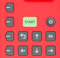 |
| POWER |
Pressure insensitive and slightly recessed to prevent accidental shutdown To turn the system on, push and hold the power button for up to 2 seconds. |
|
| START |
LED Backlit for additional functionality Press once to create a Marker Press and hold to create a new passings file. |
LED Backlight Green - System has GPS fix, active loop or ground antenna connected and either a Cloud connection or connection to a local RACE RESULT 12 instance. Orange - Loading and confirmation of new passings file creation |
| OK | Select or confirm menu items | |
| BACK | Return to the previous menu or cancel current action | |
| Directional Buttons (Up, Down, Left, Right) |
Use Up/Down to scroll through different display screens. Additionally used to interact with menu items / inputs |
|
|
Navigation Buttons |
Correspond to menu items on the display. | |
Status LED
The status LED is located to the top right of the display, above the navigation keys. The LED can be illuminated in either green or red, this is used by the system to indicate certain system actions or errors.
The green LED is used for the Passing Indicator.
A flashing red LED is used to alert that an error has occurred, this can be viewed in the Error Log, opening the error log will clear this warning.
A solid red LED is shown when a timing error occurs such as a Loop Error, and is accompanied by a beep as an audible warning. The LED will be solid red for 5 seconds after the error occurs, and will then revert to the flashing state.
The brightness of the LED can be set in the General Settings menu and at full brightness can be seen even in bright daylight.
Water Resistant Flap
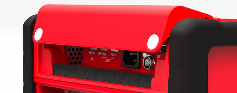
The water resistant flap on the front side of Ubidium is used to protect the port compartment from water, dirt and dust.
The flap is designed so that it cannot be left in an open state and will close under it's own weight. Two additional magnets in the bottom corners keep the flap closed and provide additional closing power when cables are exiting the compartment.
The lower edge of the flap is protected by a brush through which cables can easily fit whilst still keeping out unwanted intrusion.
A drainage channel runs along the back edge of the compartment allowing water to drain to the left and right of the compartment. This is further sealed with a foam pad along the back edge of the lid.
Additionally the flap protects the ventilation grilles for the internal ventilation system. The right grille (inlet) contains a filter which can be removed for cleaning / servicing.
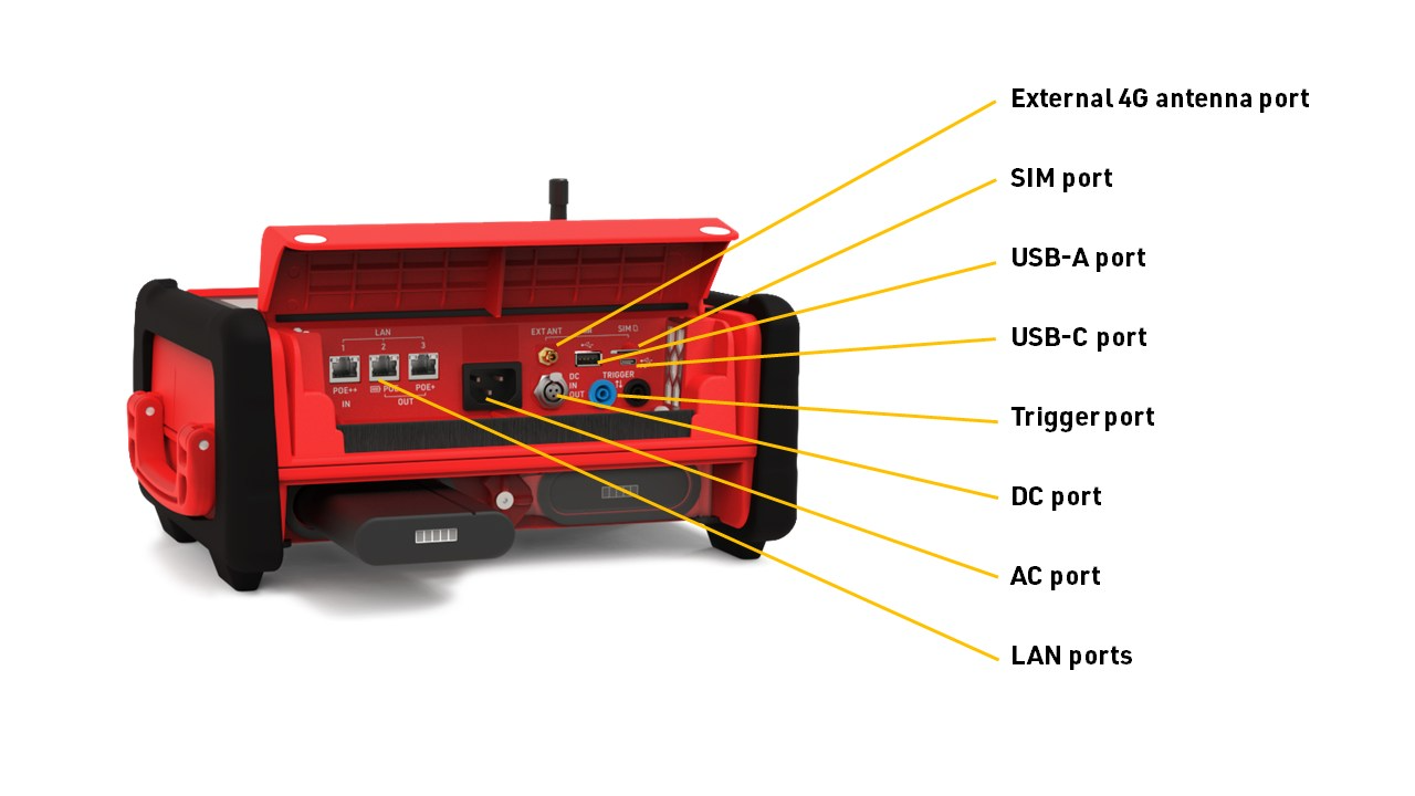
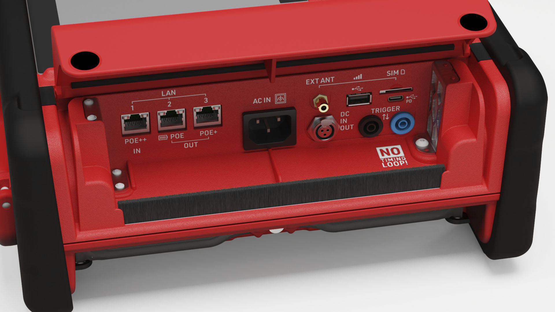
Port Compartment
Power and data communication ports for Ubidium are located under the Water Resistant Flap.
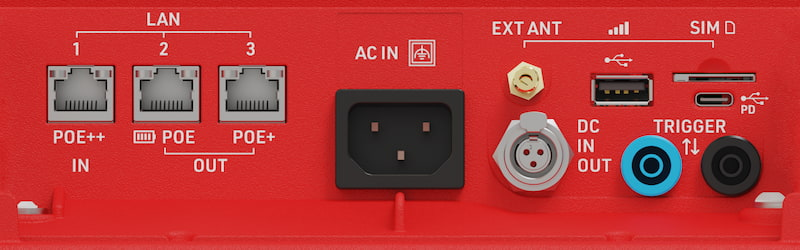
| LAN Ports |
Provides networking (see: LAN / Ethernet Network Settings) Power in / out via POE (see: Power Over Ethernet (PoE)) |
| USB-A | For retrieving data from the system |
| USB-C |
Provide power to the system (see: USB-C Power Delivery) |
| SIM Card |
External SIM card slot (see: External SIM Settings) Accepts 2FF SIM cards |
| External 4G/LTE Antenna | Connect an external antenna boost signal strength of 4G / LTE mobile networks. |
| AC Port | Power supply, 110-240V AC, 50/60Hz |
| DC Port | DC Power in / out (see: DC Power) |
| Trigger Port |
For connecting third party timing devices (see: Trigger Port) This must not be used for connecting a Loop Cable for Active timing. |
Regulatory Compliance
 |
Only use shielded ethernet cables with the system such as those rated CAT6 S/FTP |
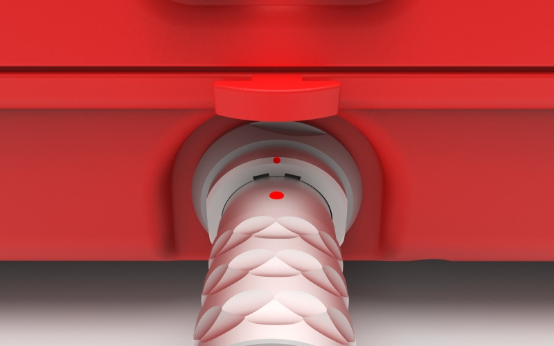
Timing Connectors
There are three connectors on the rear of the system which are used for timing, in addition to the Trigger Port which is located in the main port compartment.
The Active Loop Port and Expansion port are both protected by the rubber port cover for transport or when not in use, and the Active Timing Antenna should also be folded down in to the slot when not in use to protect it from damage.
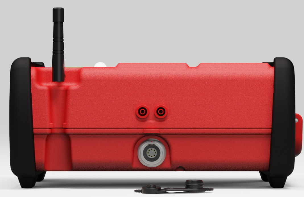
Active Loop Port
The Active Loop Port (two red banana jacks) is used to connect a Loop Cable when using Ubidium as an Active System.
Ubidium can support loop cables between 5 meters (~16 ft) and 60 meters (197 ft) in length, which should be setup with a width between 30cm (11 inches) and 60cm (22 inches).
Longer cables may result in power degradation which will inhibit the ability of the system to provide 100% Loop Power.
|
Only connect RACE RESULT Loop Cables to the Active Loop Port. Do not connect any external power source through the Active Loop Port. |
Active Timing Antenna
The Active Timing Antenna is used for 2.4Ghz with Active Transponders when using Ubidium as an Active System.
When not in use this should be folded down in to the storage slot on the case of the system, it is not necessary to disconnect this antenna.
Trigger Port
The trigger port (black and blue banana jacks) can be used to connect to third-party timing devices to either receive or send timing impulses. These are a pair of standard 4mm banana plugs.
Devices used to record impulses should be normally open and close the circuit to create the trigger, the impulse must be LOW for a duration of at least 1ms (0.001s). If recording multiple consecutive triggers, then the impulses must be 10ms apart (0.01s).
The trigger port cannot be used to connect a Loop Cable for timing.
| Blue | Black | |
| Polarity | + (Positive) | - (Negative) or GND |
Expansion Port
The expansion port is used for connecting the Ubidium Ground Antenna.
Internal Modules
Ubidium contains the following internal modules, these cannot be accessed directly but their settings and functionality are available through the corresponding settings.
Wi-Fi
Ubidium includes Wi-Fi capability using an on-board Wi-Fi module, this Wi-Fi is separate from the 2.4 GHz used for active timing, and does not have any external antenna port.
The Wi-Fi supports both 2.4 GHz and 5 GHz networks, and can act as both a client and access point. When operating in client mode then 5 GHz will always be preferred to prevent interference with the 2.4 GHz used for active timing.
The Wi-Fi settings are configured through the Network Settings menu.
Internal SIM card
All Ubidium systems include a pre-installed, secondary internal SIM card which can be used for remote support when necessary.
Currently this modem cannot be used to connect to servers for uploading status or timing data.
Note that the SIM card cannot be accessed and must not be removed from the system.