The Ubidium System contains the main computing logic and interface for timing with Ubidium.
The system integrates all the components required including batteries and power management, the user-interface with display and keypad, 4G / LTE modem, ports for networking and connectivity, timing connectors and more. No external accessories are needed with Ubidium.
Ubidium stores all data on its built-in memory, this can then be accessed by scoring software, such as RACE RESULT 14, or uploaded directly to a cloud-based server.
The system ensures uninterrupted operation as it runs independently from any other computer or external power supply.
System Components
Ubidium is an entirely self-contained unit, with all the required components accessible directly on the exterior of the shell. The system is designed to ensure all components are protected from water ingress / damage, and does not require any additional cover or lid.
The system is primarily constructed from a highly durable PLASTIC TYPE, designed to withstand the, sometimes, harsh conditions of sports events.


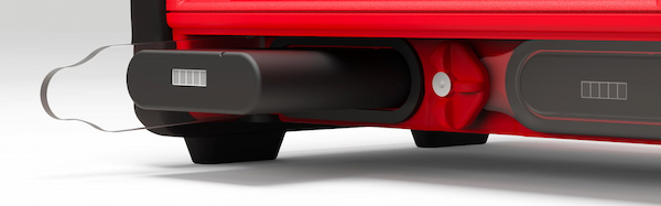
The base of the system features recessed text "THIS SIDE DOWN" and the system should always be setup accordingly to prevent water ingress. Additionally on the base are 4 mounting screw holes for permanent installations, if mounting to a wall then this should be done with the front side facing down.
Ubidium contains an active ventilation system which will be triggered in hot temperatures or in high humidity environments to prevent the formation of condensation on sensitive components.
A handle on the left side can be used to carry the system.
Bumpers
Two rubber bumpers provide additional drop / fall protection to Ubidium, these also elevate the system from the ground with the feet on the bottom side.
The rubber bumpers are additionally designed with a curved profile on the back side to prevent Ubidium from being stood with the Water Resistant Flap facing upwards.
When removing / installing the rubber bumpers it is important to ensure the correct orientation is used. The left and right bumpers must be installed accordingly, this can be identified by the cutouts towards the front side both top and bottom.

Battery Compartments
The front side of the system contains two battery compartments for installing supported battery units.
Each compartment is covered by a transparent Polycarbonate cover, this ensures the current battery status can always be seen visually without opening the system. Each compartment is also sealed with a foam pad around the edge of the opening, this creates a seal with the compartment flap.
To unlock the compartments turn the center locking knob either clockwise or anti-clockwise to align the cut-out edge with the compartment you wish to open.
Batteries must be entered in the correct orientation, aligning the cutout ridge with the notch in the top side.
The batteries can safely be removed at any time.
Display
Ubidium contains a 6.2" integrated backlit display designed to be readable in any conditions when switched on.
The display is protected by a high-impact thermally tempered glass, additionally the ridges above and below the screen prevent large objects from crushing the screen.
The display is designed to be readable whilst standing over the device normally.
Keypad
The keypad of Ubidium is completely sealed inside the top case of the system, rubber keys cover the tactile switches below making the buttons easy to use in all conditions.
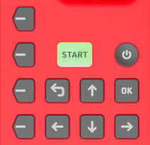 |
| POWER |
Pressure insensitive and slightly recessed to prevent accidental shutdown To turn the system on, push and hold the power button for up to 2 seconds. |
|
| START |
LED Backlit for additional functionality Press once to create a Marker Press and hold to create a new passings file. |
LED Backlight Green - System has GPS fix, active loop or ground antenna connected and either a Cloud connection or connection to a local RACE RESULT 14 instance. Orange - Loading and confirmation of new passings file creation |
| OK | Select or confirm menu items | |
| BACK | Return to the previous menu or cancel current action | |
| Directional Buttons (Up, Down, Left, Right) |
Use Up/Down to scroll through different display screens. Additionally used to interact with menu items / inputs |
|
|
Navigation Buttons |
Correspond to menu items on the display. | |
Status LED
The status LED is located to the top right of the display, above the navigation keys. The LED can be illuminated in either green or red, this is used by the system to indicate certain system actions or errors.
The green LED is used for the Passing Indicator.
A flashing red LED is used to alert that an error has occurred, this can be viewed in the Error Log, opening the error log will clear this warning.
A solid red LED is shown when a timing error occurs such as a Loop Error, and is accompanied by a beep as an audible warning. The LED will be solid red for 5 seconds after the error occurs, and will then revert to the flashing state.
The brightness of the LED can be set in the General Settings menu and at full brightness can be seen even in bright daylight.
Water Resistant Flap
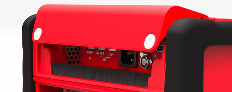
The water resistant flap on the front side of Ubidium is used to protect the port compartment from water, dirt and dust.
The flap is designed so that it cannot be left in an open state and will close under its own weight. Two additional magnets in the bottom corners keep the flap closed and provide additional closing power when cables are exiting the compartment.
The lower edge of the flap is protected by a brush through which cables can easily fit whilst still keeping out unwanted intrusion.
A drainage channel runs along the back edge of the compartment allowing water to drain to the left and right of the compartment. This is further sealed with a foam pad along the back edge of the lid.
Additionally the flap protects the ventilation grilles for the internal ventilation system. The right grille (inlet) contains a filter which can be removed for cleaning / servicing.
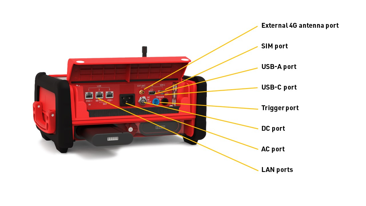
Port Compartment
Power and data communication ports for Ubidium are located under the Water Resistant Flap.
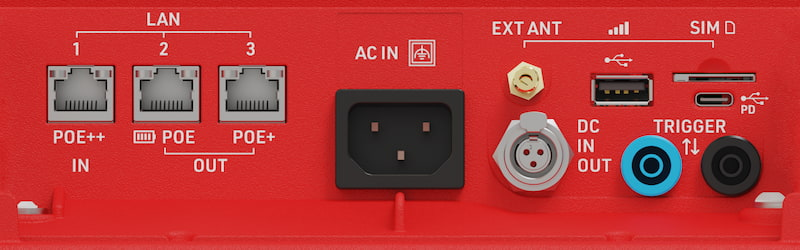
| LAN Ports |
Provides networking (see: LAN / Ethernet Network Settings) Power in / out via POE (see: Power Over Ethernet (PoE)) |
| USB-A | For retrieving data from the system |
| USB-C |
Provide power to the system (see: USB-C Power Delivery) Provide local data connection |
| SIM Card |
External SIM card slot (see: External SIM Settings) Accepts 2FF SIM cards |
| External 4G/LTE Antenna | Connect an external antenna to boost signal strength of 4G / LTE mobile networks. |
| AC Port | Power supply, 110-240V AC, 50/60Hz |
| DC Port | DC Power in / out (see: DC Power) |
| Trigger Port |
For connecting third party timing devices (see: Trigger Port) This must not be used for connecting a Loop Cable for Active timing. |
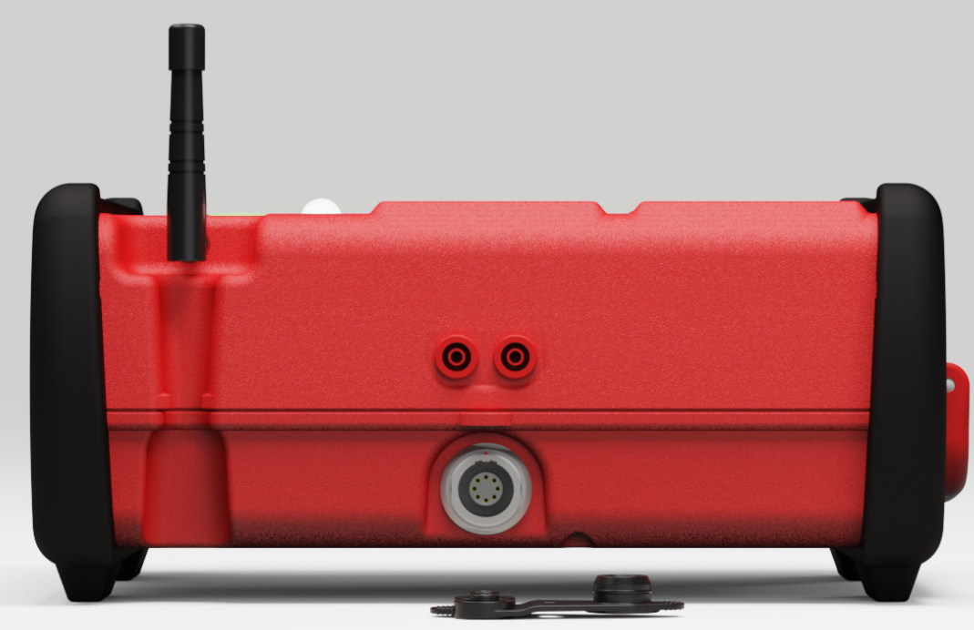
Timing Connectors
There are three connectors on the rear of the system which are used for timing, in addition to the Trigger Port which is located in the main port compartment.
The Active Loop Port and Expansion port are both protected by the rubber port cover for transport or when not in use, and the Active Timing Antenna should also be folded down into the slot when not in use to protect it from damage.
Internal Modules
Ubidium contains the following internal modules, these cannot be accessed directly but their settings and functionality are available through the corresponding settings.
Power & Battery
Ubidium contains a power management system which is used to charge the batteries and also ensure the system operates without interruption even when power sources are changed.
Some power connectors can also be used to provide a power output to power secondary devices.
Batteries
Ubidium uses smart 94 Wh Lithium-ion batteries which are installed into the Battery Compartments.
RACE RESULT batteries contain a custom firmware adapted specifically to the requirements of the system and can be purchased either directly through the RACE RESULT Shop or through www.inspired-energy.com (request product number NH2054RR34).
The batteries will be charged by the system when connected to an external power supply.
Batteries in Ubidium are "hot-swappable" meaning that they can be removed and replaced without the system shutting down provided that at least one battery or external power supply remains connected.
Each battery contains an LCD display on the front to indicate the remaining charge.
| Battery Level | Indicator |
|
<5 % |
No Bars |
| >5 % |  |
| >25 % |  |
| >45 % |  |
| >60 % |  |
| >80 % |  |
Expected battery life is as follows according to the number of batteries and different use cases.
| 1 Battery | 2 Batteries | Power Consumption* | |
| Active Timing (50 % Loop Power) | 13.4 h | 26.9 h | 7 W |
| Passive Timing (4.6 m Antenna / 6 Segments) | 6.7 h | 13.4 h | 14 W |
| Passive Timing (7.7 m Antenna / 8 Segments) | 4.7 h | 9.4 h | 20 W |
| Passive Timing (15.4 m Antenna / 16 Segments) | 2.8 h | 5.7 h | 33 W |
| Passive Timing (23 m Antenna / 30 Segments) | 2 h | 4 h | 47 W |
*Not charging, 4G upload enabled, no ethernet.
Power performance may be reduced above 25 °C (77 °F) / in strong sunlight.
Due to manufacturing processes and differences in the internal cells, the exact capacity of each battery may vary, the exact capacity of each specific battery will be shown on the smaller product label on the rear of each battery. This will always be 94 Wh or higher, but should never exceed 100 Wh in order to comply with international safety regulations.
AC Power
The AC power supply supports 110-240V AC power supply.
When used outdoors, it is recommended to use the supplied, right-angled, connector to ensure the flap can close completely whilst connected to AC Power.
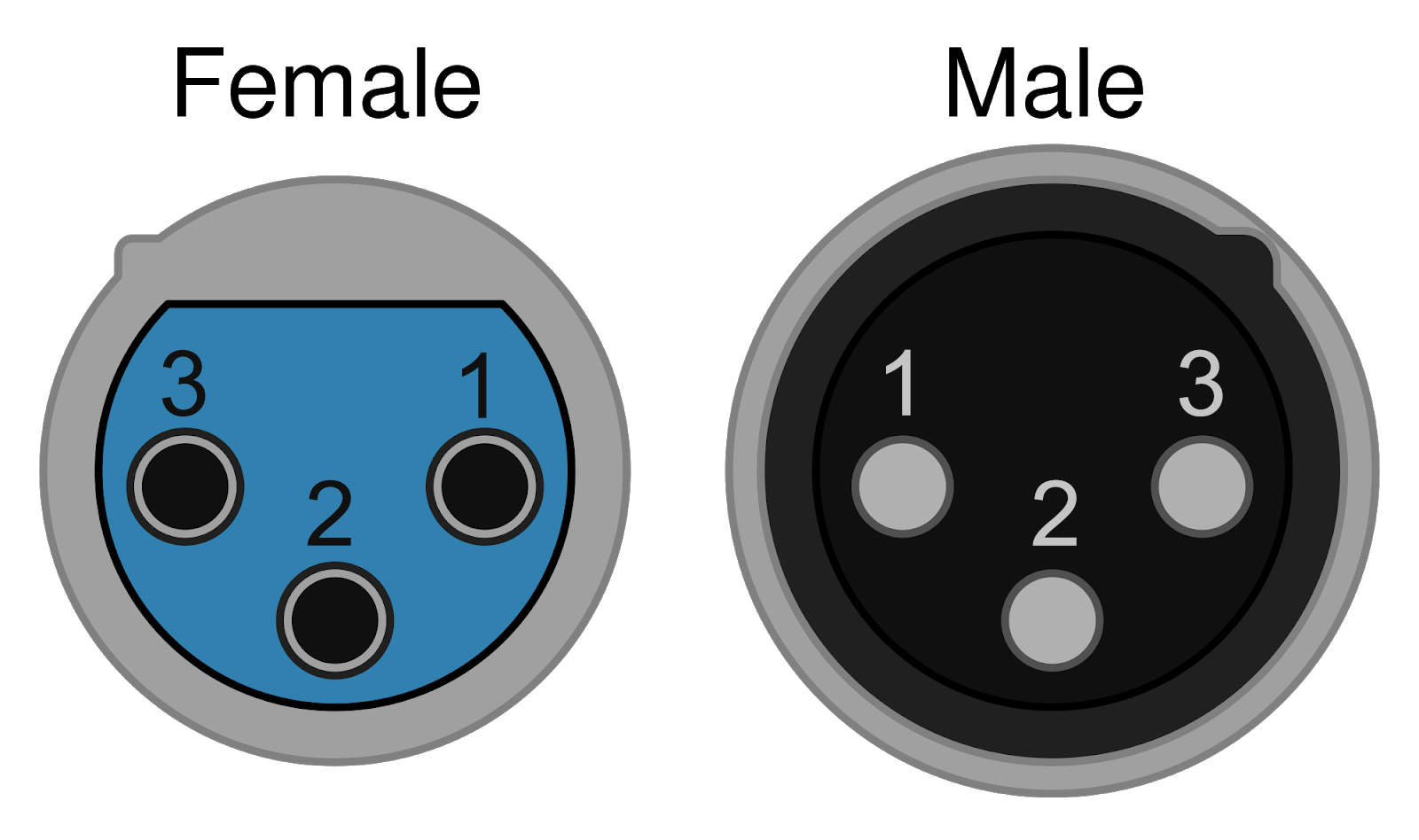
DC Power
The DC Power port is a Female 3-Pin Mini XLR Jack which supports both DC power in and DC Power Out.
| DC In | 11 - 16 V (5 A) | Max 100 W |
| DC Out | 11-16.8 V (2.3 A fuse) |
25W @ 11 V (Empty internal battery) 40W @ 16.8 V (Full internal battery and AC power supply) |
When DC OUT is enabled then the current voltage of the internal batteries will be sent out continuously.
| Pin 1 | Pin 2 | Pin 3 |
| DC IN | GND |
DC OUT |
Power Over Ethernet (PoE)
Ubidium supports both power input and power output via Power over Ethernet (PoE). To ensure consistent information, please refer to the Ubidium Datasheet for exact power ratings and supported standards.
Each ethernet port has different capabilities as follows:
| LAN 1 | PoE++ Input | Used to power the Ubidium system via a compatible PoE power source. |
| LAN 2 | PoE Output | Provides power to external devices. This port is always active when Ubidium is powered on and can operate from the internal battery. |
| LAN 3 | PoE+ Output | Provides power to external devices. This port is only active when Ubidium is connected to an external power supply (AC or PoE++ input). |
It is possible to power a secondary Ubidium system using the PoE+ output from LAN 3; however, this does require a sufficient external power input to the system. Note that this daisy-chaining cannot be extended further, as the power delivery to the secondary system will not be sufficient to power a third.
The Green LED on the left of each PoE port indicates the status of the PoE OUT, the following patterns indicate the function of the port.
| Always Off | PoE disabled or not functioning |
| Blinking |
Searching or ready for input/output |
| Always On | Device detected and powered |
Note that devices using a passive PoE input will not work when connected directly to Ubidium, such devices will require an 802.3af (or equivalent) adapter.
External Battery Charger
Ubidium batteries can additionally be charged using an external charging unit.
RACE RESULT offers two variations which can be ordered directly through the Shop, supporting either 2 or 4 batteries.

Additional options are available for up to 12 batteries and can be ordered directly from Inspired Energy, when ordering please provide the product number NH2054RR34 to ensure compatibility.
Startup Process
To power on Ubidium, firmly press and hold the power button until the status LED illuminates green.

Ubidium will now commence the startup process, during this time it will load existing passings from the system and search for a GPS signal. Additionally, if the system is set to enable a cloud connection during startup then it will begin to attempt to connect via any available network connection.
Pressing the Start button will skip waiting for any additional jobs.
Once the Startup process is complete, skipped, or if the timeout is reached, Ubidium is ready to begin timing and will automatically start recording all passings.
If the system has previously found an available Firmware Update then it will show an alert that an update will be available to install during the next shut down.
To turn off the system press the power button and then again when prompted to confirm the shutdown.
Note that even in an powered off state Ubidium will show the current battery state on the display, the power drain in this state is minimised so should not impact negatively on the battery life of the system.
User Interface
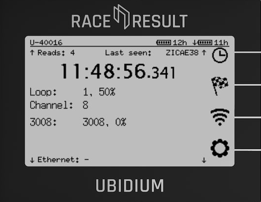
The main screen of the system when powered on shows the system time, some fixed system information, the available menu items and some additional information about either the current timing status, network or passing information.

The top row contains the system name and current battery status, the top and bottom display a preview of the next / previous timing information screen.
Battery Status
The current charge level of each battery is shown.
An arrow indicates the charge status for each battery
 |
Battery is charging Time remaining until fully charged |
 |
Battery is discharging Time remaining until empty |
 |
Battery is not currently in use |
Text Input (With Keyboard)
Settings which accept a text input will open a keyboard when editing the setting.

The keyboard can be controlled using the keypad on the device. If connected to the same network as Ubidium or to the system Access Point you can scan the on screen QR code to access the system browser interface which will also provide a text input to directly edit the text using your device.
System Data Screens
There are 3 datasets that can be displayed in the system data area, these can be cycled using the up/down arrow keys. Additionally a short preview of each hidden view is shown at the top / bottom of the screen.
Timing Status
Active Loop Information
Current system Loop and Channel IDs are shown with the loop power.

Additional systems on the same channel within range are also shown below.
Loop Boxes in range in repeat mode will be listed below with the Loop ID and Loop Power.
Passive Antenna Information
Currently connected antennas are shown with their corresponding antenna number. A solid antenna indicates the antenna is currently detecting a transponder.

If a letter is displayed instead of the antenna number then the antenna is currently reporting an error, the possible errors are as follows:
- B - Bad: The antenna reports some bad monitoring values (most commonly from reflections or obstructions from items placed on the antenna, or from an incorrectly mounted mat cover)
- ? - Unavailable: A previously connected antenna is no longer communicating with the System
- M - Mute: Can occur shortly after booting before an antenna is ready for operation
- U - Update: The element is undergoing a firmware update and will be available again soon
- (empty): Element is unresponsive but is still able to pass through data and power
- ! - Unknown Error: This should be reported to RACE RESULT for further diagnosis
Passing Information
Passing information displays the current last reads on the left side. If the detections are within 1 second of the last timestamp displayed then a gap will be shown rather than the full time.
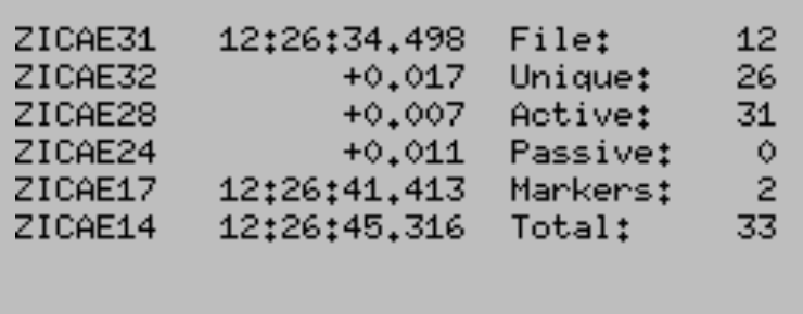
Additionally displayed on the right side is data relating to the current passings file:
- File Number
- Unique Transponders seen
- Active passings recorded
- Passive passings recorded
- Markers recorded
- Total passings recorded
Networking Information
Current connection status for Ethernet, Wi-Fi, Mobile (GSM) and Cloud Connection, for network connections, there are three possible icons.
- Black cloud - This connection is currently being used to connect to the internet
- Cloud outline - This connection has an internet connection available but is not currently being used
- Crossed out cloud - No internet connection is available on this network'
This is followed by the IP address for the ethernet and Wi-Fi connections and additional mobile network information for the mobile connection.
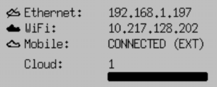
When the Cloud upload is enabled then the count of passings which have been uploaded will be displayed below and the status bar will also indicate the percentage of passings which have been uploaded.
The mobile status will also indicate whether it is using the internal or external SIM card. Note that unless the internal SIM has been explicitly unlocked for the system it will not be able to connect to the cloud using the internal mobile connection.
Settings Menus
From the main screen 4 menu icons are displayed, clicking the corresponding navigation key will open the corresponding menu. Clicking the back key from the main screen will also show the label for each menu.

Inside the menu any sub-menus of that item are shown below, sub-menus and menu items can be accessed by clicking the corresponding navigation key.
If an error has occurred then the General Settings icon may display an exclamation mark, this will be cleared when opening the Error Log.
Timing
Time Base
Ubidium always uses time of day to record times, the timebase of Ubidium is maintained by an internal clock with an accuracy of 0.28ppm when powered on, this is equivalent to a maximum drift of 0.024s per day.
By default Ubidium will use GPS time when available, during the Startup Process Ubidium will automatically try to sync to GPS time, this should always be done outside in an open space, away from any buildings, when possible. It is important to ensure that the Timezone is set correctly to ensure the GPS time is correct for your location.
If a GPS time sync is obtained then the system will continuously micro-adjust the clock to ensure maximum clock accuracy.
If no accurate GPS time can be obtained the system will attempt to fallback to NTP (Network Time Protocol), this is only available if an internet connection is available.
In the event that neither GPS time or NTP time are available the system will revert to the time stored on the internal clock.
The internal clock is maintained even when the system is powered off, however this uses a RTC with an accuracy of 5ppm which gives a maximum drift of 0.432s per day when switched off. The RTC will use the internal batteries when available or a backup CR2032 battery on the main board. The backup battery has an estimated life span of 20 years even if continuously used.
Passings Files
All Ubidium timing data will be stored in a passings file on the system, each file has a unique ID which is displayed on the passing information screen.
When starting Ubidium a new passings file will automatically be created, you can additionally create a new file by pressing and holding the START button until the button is illuminated orange, the file will be created upon releasing the button.
When connecting to Ubidium only the current passings file will be used.
Ubidium passings files cannot be deleted and so are permanently stored in the on-board memory, this has no impact on performance and storage capacity should not be a concern.
Passive - UHF
TrackTiming
TrackTiming is a software module which is integrated into the Ubidium system, it provides a simple solution for continuous timing of circuits and A-B courses. It is primarily designed for lap events and training sessions where participants may complete multiple laps or make multiple runs over a fixed course.
As TrackTiming is integrated into the Ubidium system, it can be accessed through any computer or mobile device which is connected to the system.
TrackTiming Features
- Fully integrated within the Ubidium system
- Persistent participant database meaning participants only need to register a single time
- Create multiple sessions of races for each event
- Time-based transponder assignments for specific events or races
- Ability to allow participants to access TrackTiming for direct access to registration and results screens
Firmware
Ubidium firmware updates can be downloaded directly to the system when connected to the internet via any available method. When a new version is released, it will be rolled out gradually to systems with increasing availability from the date of release.
Note that it is therefore possible that systems will receive updates at different times and, even if systems are online at the same time, one system may find an available update whilst others do not. The gradual rollout system does not apply when checking for updates manually - allowing updates to be installed immediately when available.
The below information is applicable to firmware versions 1.5.8 and above.
Checking For Updates
By default Ubidium will automatically check for regular firmware updates in the background when connected online, but will not download the firmware package until instructed (except for critical updates - see below). The Ubidium will show a notification that a new firmware update is available.
Alternatively this can be changed to manual update mode which will require triggering a check manually through the Firmware Settings menu. When set to manual - if no update is installed for a period of 90 days then this will revert to a semi-automatic mode to check for updates. If any update older than 90 days is found then the system will switch to automatic mode and cannot be switched to manual mode until the update is completed.
The manual check will list all available firmware updates.
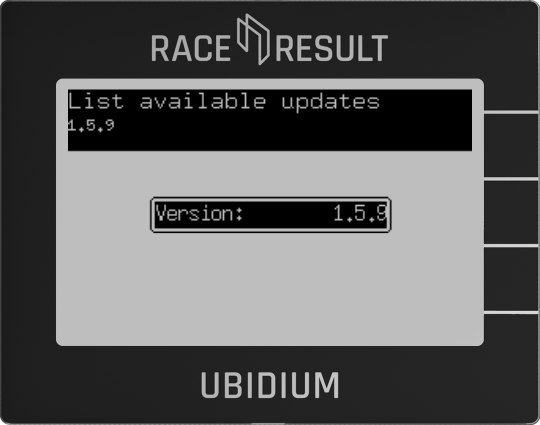
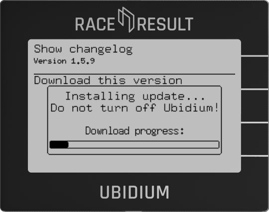
Selecting a version will allow you to review the changelog for that version and start the download.
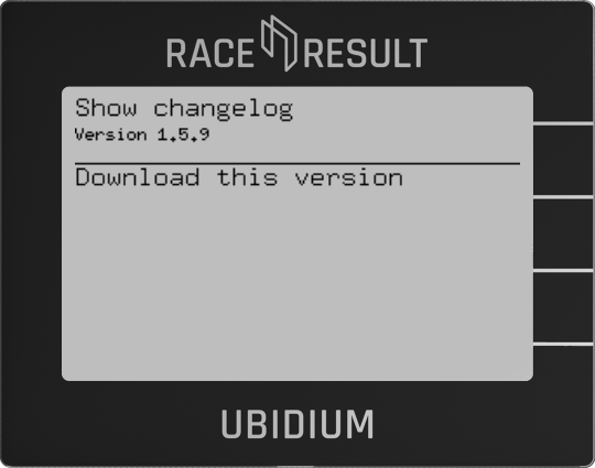
Download & Install
If a firmware update is available (in auto check mode) then during the shutdown process a selection window will be displayed to either download and install or decline the update.
If the update is declined then the system will prompt again on each subsequent startup and shutdown of the system.
When downloading an update a progress bar is shown, and once the update is downloaded then the Ubidium will show a prompt to shutdown or restart the system, new firmware versions will only be applied on the next restart of the system.
Long-Running Systems
An Ubidium system will automatically be flagged as long-running if it has been switched on and running continuously for a period of more than 10 days.
When in the long-running state then the top bar of the screen will display a notification if an update is available, this will be accompanied by an audible warning every 6 hours if it has been more than 24 hours since the update was found.
The top bar message will be suppressed if set to manual check mode, however this will still revert to automatic following the same logic as a regular system.
Critical Updates
As of June 2025 - no critical updates have been released for Ubidium.
Critical updates are versions which are considered of the highest importance to ensure systems remain functional. Ubidium systems will always check for critical updates automatically when connected online and these updates will always be downloaded immediately when available.
If a critical update is downloaded then it will be applied in the background and will be available after the next restart, a notification will be shown during the shutdown process stating when this occurs.
For long-running systems an alert will be displayed in the top bar and an audible warning will be given every 15 minutes if the update is not applied with a restart within 1 hour of the initial alert.
Technical Specifications
Safety Regulations & Compliance
General Safety Responsibilities
To maintain this condition and to ensure safe operation, the user must observe all instructions and warnings given in this operating manual.
Applicable local and national safety regulations and rules for the prevention of accidents must be observed in all work performed.
Human RF Exposure
To comply with exposure requirements of the EU, US, Canada, and Japan, this device must be operated at a minimum distance from all persons of at least 30cm/1ft.
FCC Statement
FCC 15.21
Changes or modifications not expressly approved by the party responsible for compliance could void the user’s authority to operate the equipment.
FCC 15.19
This device complies with Part 15 of the FCC Rules. Operation is subject to the following two conditions:
(1) This device may not cause interference.
(2) This device must accept any interference, including interference that may cause undesired operation.
FCC 15 Subpart B
This equipment has been tested and found to comply with the limits for a Class B digital device, pursuant to part 15 of the FCC Rules. These limits are designed to provide reasonable protection against harmful interference in a residential installation. This equipment generates, uses and can radiate radio frequency energy and, if not installed and used in accordance with the instructions, may cause harmful interference to radio communications. However, there is no guarantee that interference will not occur in a particular installation. If this equipment does cause harmful interference to radio or television reception, which can be determined by turning the equipment off and on, the user is encouraged to try to correct the interference by one or more of the following measures:
- Reorient or relocate the receiving antenna.
- Increase the separation between the equipment and receiver.
- Connect the equipment into an outlet on a circuit different from that to which the receiver is connected.
- Consult the dealer or an experienced radio/TV technician for help.
Contains FCC ID: TFB-1004 and XMR201903EG25G
IC Statement
RSS GEN Issue 5
This device contains licence-exempt transmitter(s)/receiver(s) that comply with Innovation, Science and Economic Development Canada’s licence-exempt RSS(s). Operation is subject to the following two conditions:
(1) This device may not cause interference.
(2) This device must accept any interference, including interference that may cause undesired operation of the device.
Cet appareil contient des émetteurs / récepteurs exemptés de licence conformes aux RSS (RSS) d'Innovation, Sciences et Développement économique Canada. Le fonctionnement est soumis aux deux conditions suivantes:
(1) Cet appareil ne doit pas causer d'interférences.
(2) Cet appareil doit accepter toutes les interférences, y compris celles susceptibles de provoquer un fonctionnement indésirable de l'appareil.
Japan Statement
This equipment contains specified radio equipment that has been certified to the Technical Regulation Conformity Certification under Radio Law.
Warnings and Cautions
The following alerts are used in this manual:
- WARNINGS alert users of potentially dangerous situations.
- CAUTIONS alert users of potential equipment damage.
Warnings and cautions are indicated by:
- the text WARNING or CAUTION,
- a description explaining the hazard and how to avoid it,
- an icon:

Where to Operate the System
The RACE RESULT Active System uses universal frequencies that can be used globally.