Ubidium
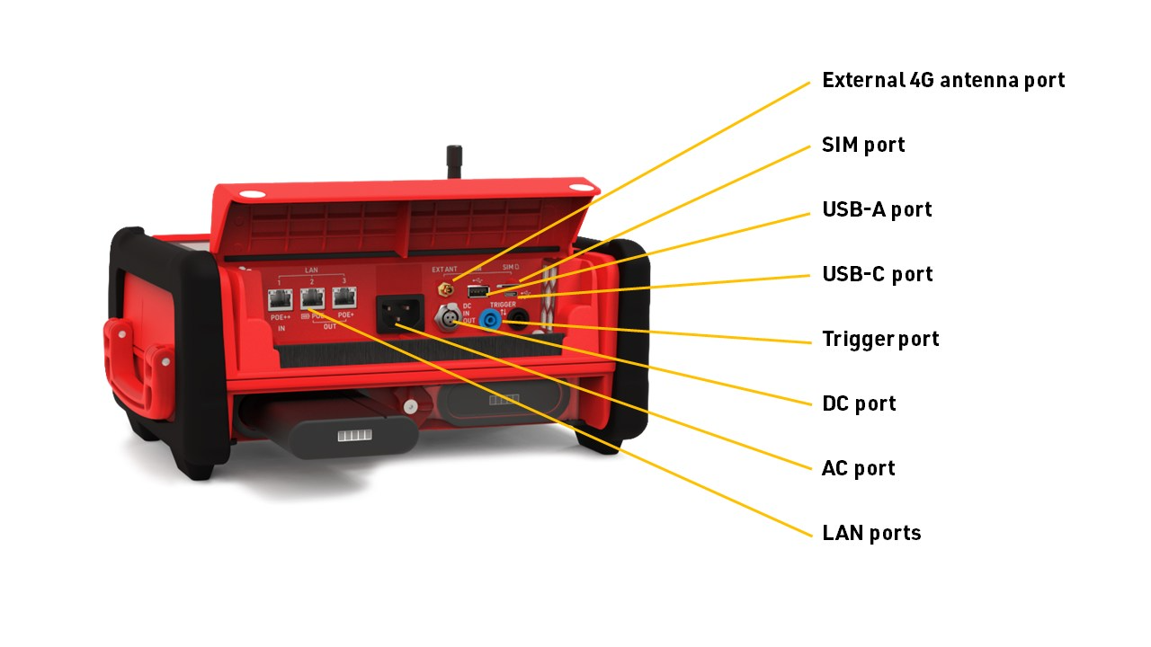
Ubidium is the most advanced timing system available with support for both Active and Passive timing with unbeatable battery life and connectivity. Below is an overview of the elements of Ubidium, some of these will be referenced later in the guide.
System Overview



Starting the System
To power on Ubidium, firmly press and hold the power button until the status LED illuminates green.
Ubidium will now commence the startup process, during this time it will begin to search for a GPS signal, Ubidium will automatically set the time using GPS when available. When using GPS time, the time zone of the system will also be set automatically based on the GPS location.
Once the Startup process is complete, or if the timeout is reached, you should check the time which is displayed, if the time is incorrect then please refer to the guide below for troubleshooting the time.
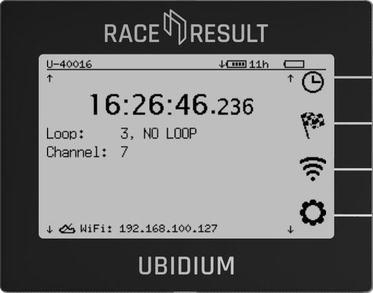
Ubidium is now ready to begin timing and will automatically start recording all passings, the Start Button will be illuminated green if the system has GPS time sync, an Active Loop connected and either a successful cloud connection (via SIM, Wi-Fi or Ethernet), or a connection to a locally networked instance of RACE RESULT 12.
Active Timing Setup
When being used as an Active system a Loop Cable is used to activate the Transponders which generate the times.
This loop cable must be secured to the ground, covering the full width of your timing point, it is important to ensure that the loop cable is setup correctly to ensure reliable and accurate recording of times. The Loop Cable is connected to the Active Loop Port on the back of the system , NOT the Trigger port under the flap. You additionally need to raise the black 2.4 GHz antenna so this is pointing vertically up, this is used to receive data from the transponders.
Loop Cable Setup
The loop cable should form a rectangle with a width of 60cm, the exact line on which you wish to record a time should be positioned across the middle of the length of the loop.

Normally the loop cable will be fixed to the ground using duct tape along the length of the loop, or covered with a mat to secure it in place. Loops can be buried in the ground, particularly for motorsports or on soft surfaces, when doing so it is common practice to protect the loop using some sort of pipe.
Where possible use a loop of exactly the required length, never coil any excess loop cable since this can cause interference resulting in transponders not being activated. Loop cables cannot be installed on metal surfaces, this will completely inhibit the loop signal meaning no passings will be generated.
Loop Settings
Depending on where transponders are being worn or mounted, and the setup of your loop, it may be necessary to check the system settings to adjust the detection height of the loop. This is done by adjusting the Loop Power setting.
To open the settings for the Active Loop, press the Navigation Button second from the top, this opens a menu for Detection Settings, which now has 3 options, the top one is for Active, so press the top Navigation Button to open this menu.

To change the Power value press the Navigation Button next to this menu item, you can now adjust the Power in increments of 10, from 0 to 100, by using the up and down Directional Buttons, then pressing the OK button to select a value.
A higher Loop Power will result in a higher maximum detection height, a value of zero will mean the Loop is switched off.
As a general rule you should try to ensure that the system can detect transponders at a height 50% higher than the expected maximum height of a transponder. To test the maximum detection height, walk away from the loop to a point further away than the maximum height, hold the transponder at the height you wish to test and walk across the loop at a moderate pace.
If the system generates a passing, which will be indicated by both a beep and red LED flash then the transponder was detected, if no passing was generated you may need to first move further away from the system or adjust the Loop Power.
Normally it is only necessary to change the Channel and Loop ID values if you are working with multiple systems or Loop Boxes for additional timing points. The use of Channel and Loop ID is explained in the Active Settings guide.
Connecting the System
In order to receive the times from Ubidium in your event file it will either need to be connected via the internet, or connected locally to your computer.
The below options are sorted according to ease of use.
RACE RESULT Decoder
System Overview
Starting the System
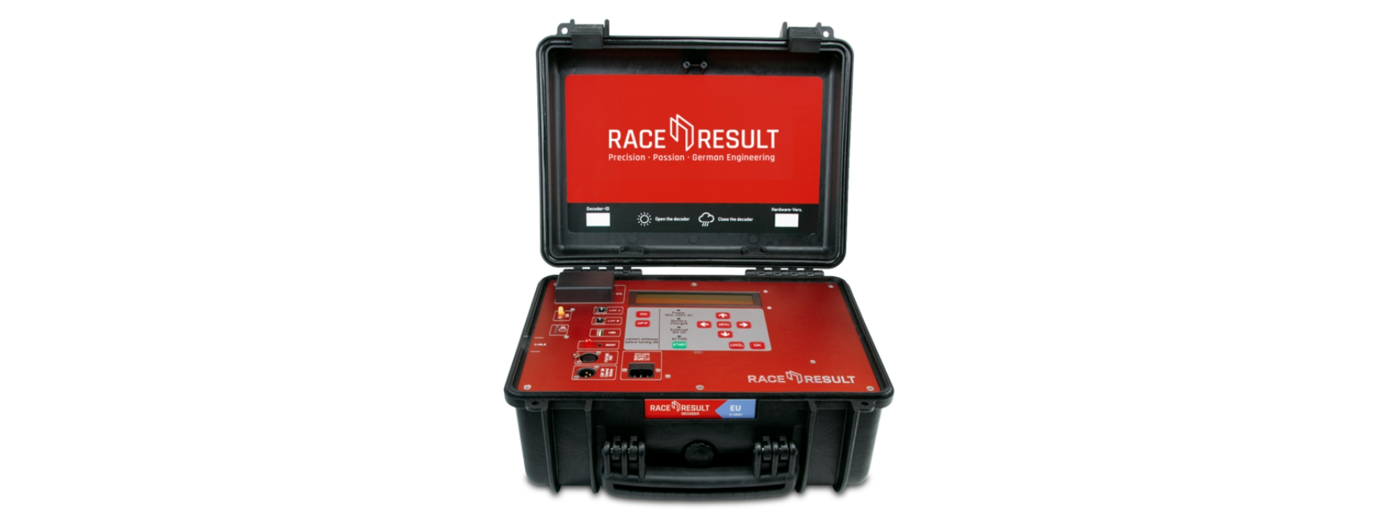
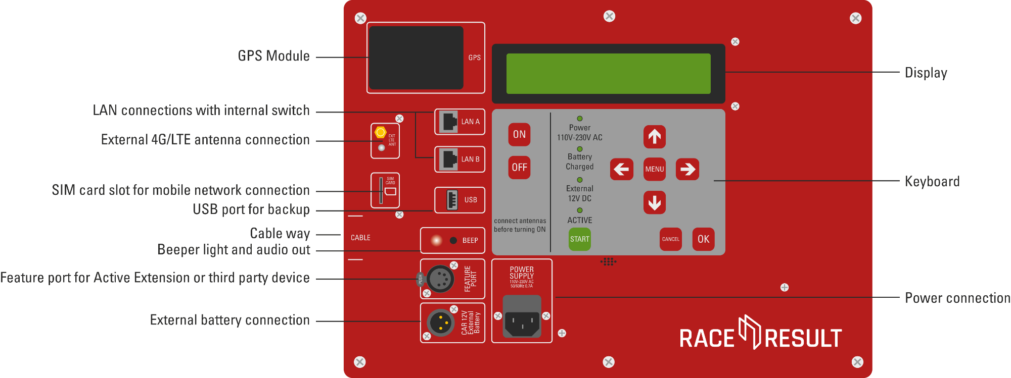
You should connect either the Passive Antenna or Active Extension to the Decoder before starting the system for optimal performance.
To power on the Decoder, press the ON button until the display is illuminated.
The boot process of the decoder may take a few minutes to initialize, especially when using Passive as the UHF reader must also be started during this time.
By default, when the system starts it will be in TEST mode and the time will not be set, the Startup Options can be changed in the system settings. When in TEST mode times are NOT stored on the system.
| N | o | P | a | s | s | i | n | g | s | T | i | m | e | : | 0 | 0 | : | 0 | 0 | : | 0 | 0 | . | 0 | 0 | 0 | |||||||||||||
| F | i | l | e | N | o | : | 1 | 0 | I | P | : | 1 | 9 | 2 | . | 1 | 6 | 8 | . | 1 | . | 2 | 0 | 0 | P | r | e | s | s | ||||||||||
| U | p | l | o | a | d | : | o | f | f | A | n | t | e | n | n | a | s | : | █ | █ | █ | █ | █ | █ | █ | █ | S | T | A | R | T | ||||||||
| U | S | B | : | n | / | a | B | a | t | t | e | r | y | : | █ | █ | █ | █ | █ | █ | █ | █ |
If the time is not set then press the Menu button and then select Time Settings, it is recommended to always use GPS time when possible.
| ➞ | S | e | t | r | u | n | n | i | n | g | t | i | m | e | : | 0 | 0 | : | 0 | 0 | : | 0 | 0 | ⬅ | |||||||||||||||
| S | e | t | s | t | a | r | t | t | i | m | e | : | 0 | 0 | : | 0 | 0 | : | 0 | 0 | |||||||||||||||||||
| S | e | t | G | P | S | t | i | m | e | ||||||||||||||||||||||||||||||
| C | o | n | f | i | g | u | r | e | G | P | S | t | i | m | e |
To set GPS time, first, select Configure GPS Time, and then set the Timezone to the correct value for your location, once set press cancel to return to the Time Settings and choose Set GPS Time. The system will now scan for GPS signal to set the time, this should be done outside in an open space away from any buildings. If the system is unable to obtain an accurate enough GPS time it may offer you to accept a less accurate time if available.
In the event that GPS time is not available, you can alternatively choose to Set Running Time from the Time Settings, you should set the time to the most accurate Time of Day possible.
As a final option, the decoder can be used without Time of Day and can run counting up from zero, however, this is not recommended as in the event of any errors it can be much harder to troubleshoot.
Once the time is set press the Menu button to return to the main screen, you must now press the green START button to enter Timing mode, the system will now create a passings file to start recording passings. When in Timing mode the ACTIVE LED will be illuminated.
To turn the system off, press and hold the OFF button until the screen shows that it is shutting down.
Passive Antenna Setup
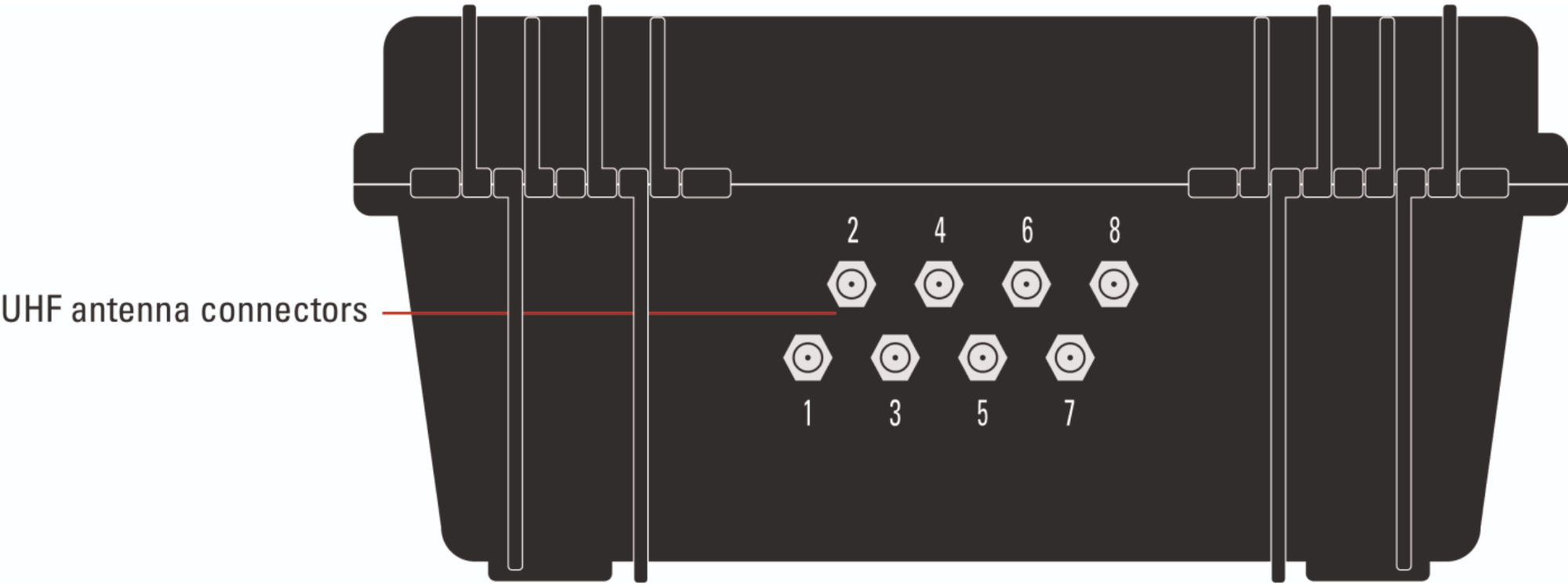
When timing with passive (UHF) the RACE RESULT Folding Ground Antenna is connected to the Decoder using the antenna ports on the rear of the system.
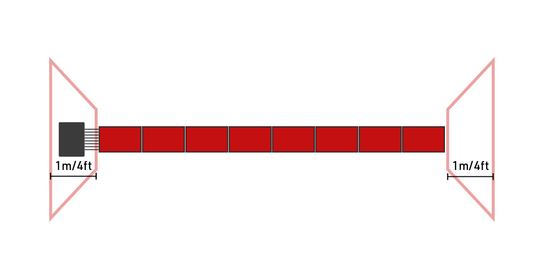
The antenna is simply unfolded to cover the width of the timing point, the standard width of the ground antenna is 4.8m, in this configuration each mat segment contains an antenna. When unfolding the antenna, ensure that the antenna cables are located on the same side as you will place the decoder, this will most likely be on the same side as your timing computer.

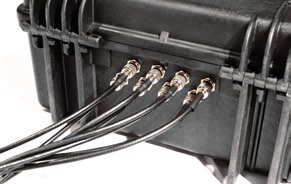
To connect the antenna cables to the decoder, line up the notches on the outside of the port with the cutouts on the cable and insert the cable, then twist 90 degrees clockwise to lock the connector in place. The antenna cables can be connected in any order.
Once the system is started the main screen will show the status of the Antenna ports.
| N | o | P | a | s | s | i | n | g | s | T | i | m | e | : | 0 | 0 | : | 0 | 0 | : | 0 | 0 | . | 0 | 0 | 0 | |||||||||||||
| F | i | l | e | N | o | : | 1 | 0 | I | P | : | 1 | 9 | 2 | . | 1 | 6 | 8 | . | 1 | . | 2 | 0 | 0 | P | r | e | s | s | ||||||||||
| U | p | l | o | a | d | : | o | f | f | A | n | t | e | n | n | a | s | : | █ | █ | █ | █ | █ | █ | O | X | S | T | A | R | T | ||||||||
| U | S | B | : | n | / | a | B | a | t | t | e | r | y | : | █ | █ | █ | █ | █ | █ | █ | █ |
A solid black bar indicates that an Antenna is connected to that antenna port. A black outline in place of the bar indicates an antenna is connected and currently detecting a transponder. An X indicates that no antenna is detected.
You should ensure that all the antennas are being correctly displayed as connected, and then additionally ensure that all the antennas detect transponders when being passed over, this is best done in TEST mode before pressing START.
When setting up your timing system you should also take the following considerations into account:
- Ensure that all participants will cross directly over the antenna - the mat should cover the full width of the timing point with no space for participants to go around it. If your timing point is wider than the mat then you may need to set up a barrier to funnel participants across the antenna.
- If your timing point is narrower than the width of the mat then you do not need to connect all the antenna cables. The antenna cables are numbered 1-8 where 1 is the element closest to the system and 8 is the furthest away, antennas which are not being used should be unplugged.
- Protect the system from unwanted intrusions - spectators may want to try and get as close as possible, particularly at the finish line. If they get too close they may stand on the system or the antenna cables which may then damage the cables or rip them out entirely. Create a barrier around the decoder to prevent any accidental damage.
- The antenna will detect all transponders within close proximity - this can include participants standing to the side either having already finished or waiting for their start. In most cases this does not cause a problem as the detections will be ignored by the software, however, it is good practice to create a 1m / 4ft buffer around the antenna to prevent unwanted detections.
- Systems should be placed a minimum of 5m apart from each other - if you are using a separate main and backup line or you have 2 timing systems located next to each other you should ensure a minimum distance of 5m between the antennas. If the fields of the antennas overlap then it can inhibit the performance of the systems to detect transponders. Additionally - for timers using EU frequencies (860-865 MHz) you may need to set the Frequencies of the two systems separately.
Active Timing Setup
When being used as an Active system, first the Active Extension is connected to the feature port of the decoder, a Loop Cable is then used to activate the Transponders which generate the times.
This loop cable must be secured to the ground, covering the full width of your timing point, it is important to ensure that the loop cable is set up correctly to ensure reliable and accurate recording of times.
Carefully screw the data cable into the Active Extension, making sure to align the pins and the black notch, then plug in the connector to the decoder until it clicks and locks in place. Connect the Loop Cable to the Banana plugs of the Active Extension and raise the black 2.4 Ghz antenna so this is pointing vertically up, this is used to receive data from the transponders.
Loop Cable Setup
The loop cable should form a rectangle with a width of 60cm (24 in), the exact line on which you wish to record a time should be positioned across the middle of the length of the loop.

Normally the loop cable will be fixed to the ground using duct tape along the length of the loop, or covered with a mat to secure it in place. Loops can be buried in the ground, particularly for motorsports or on soft surfaces, when doing so it is common practice to protect the loop using some sort of pipe.
Where possible use a loop of exactly the required length, never coil any excess loop cable since this can cause interference resulting in transponders not being activated. Loop cables cannot be installed on metal surfaces, this will completely inhibit the loop signal meaning no passings will be generated.
Loop Settings
Depending on where transponders are being worn or mounted, and the setup of your loop, it may be necessary to check the system settings to adjust the detection height of the loop. This is done by adjusting the Loop Power setting.
To open the settings for the Active Loop, press the Menu Button, and then navigate to Active Extension Settings.
| C | h | a | n | n | e | l | : | 7 | |||||||||||||||||||||||||||||||
| P | o | w | e | r | : | 0 | 4 | 0 | % | | | . | . | . | . | . | . | . | . | . | . | . | . | . | . | . | . | . | . | . | . | . | . | | | ||||||
| L | o | o | p | I | D | : | 1 | ( | B | a | s | e | ) | ||||||||||||||||||||||||||
| D | i | s | c | a | r | d | s | t | o | r | e | d | d | e | t | e | c | t | i | o | n | s | : | N | O |
To change the Power value use the arrow keys to move down to highlight the Power setting and then use the left and right arrow keys to adjust the Power value, you can adjust the Power in increments of 5, from 0 to 100, you can exit the menu by pressing Cancel.
A higher Loop Power will result in a higher maximum detection height, a value of zero will mean the Loop is switched off.
As a general rule, you should try to ensure that the system can detect transponders at a height 50% higher than the expected maximum height of a transponder. To test the maximum detection height, walk away from the loop to a point further away than the maximum height, hold the transponder at the height you wish to test, and walk across the loop at a moderate pace.
If the system generates a passing, which will be indicated by both a beep and red LED flash then the transponder is detected, if no passing was generated you may need to first move further away from the system or adjust the Loop Power.
Normally it is only necessary to change the Channel and Loop ID values if you are working with multiple systems or Loop Boxes for additional timing points. The use of Channel and Loop ID is explained in the Active Settings guide.
Connecting the System
In order to receive the times from the Decoder in your event file it will either need to be connected locally to your computer or connected to the internet to upload via the cloud.
Using cloud upload offers the easiest connection to RACE RESULT 14 when working online, as the system will be automatically shown and can be accessed and monitored from any device.