
RACE RESULT Ubidium je najpokročilejšie riešenie merania času dostupné na trhu, ktoré dokáže zvládnuť meranie času Aktívne aj pasívne (UHF) z jedného systému.
Systém Ubidium je jadrom Ubidium a používa sa na príjem údajov z radu rôznych časovacích pripojení, ako sú aktívne slučky, pozemné antény Ubidium alebo impulzné zariadenia, na generovanie údajov na základe vysoko presných palubných hodín.
Systém
Systém Ubidium obsahuje hlavnú výpočtovú technológiu a rozhranie pre meranie času s Ubidiom.
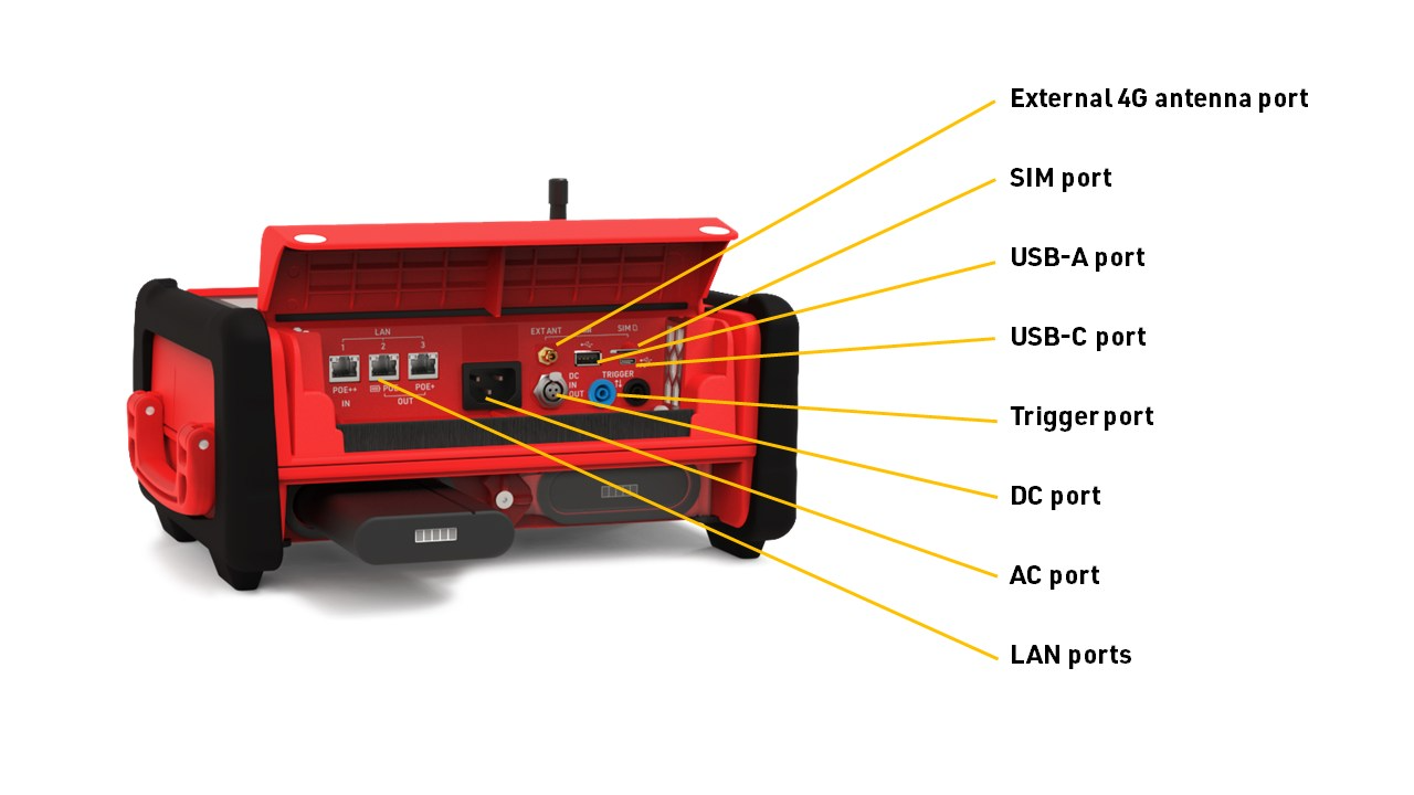
Systém integruje všetky potrebné komponenty vrátane batérií a správy napájania, používateľského rozhrania s displejom a klávesnicou, 4G / LTE modemu, portov pre sieť a konektivitu, časovacích konektorov a ďalších. S Ubidiom nie je potrebné žiadne externé príslušenstvo.
Ubidium ukladá všetky údaje do svojej vstavanej pamäte, k nim potom možno pristupovať pomocou vyhodnocovacieho softvéru, ako je RACE RESULT 12, alebo ich nahrať priamo na cloudový server.
Systém zaisťuje nepretržitú prevádzku, pretože beží nezávisle od akéhokoľvek iného počítača alebo externého zdroja napájania.
System Components
Ubidium is an entirely self-contained unit, with all the required components accessible directly on the exterior of the shell. The system is designed to ensure all components are protected from water ingress / damage, and does not require any additional cover or lid.
The system is primarily constructed from a highly durable PLASTIC TYPE, designed to withstand the, sometimes, harsh conditions of sports events.


The base of the system features recessed text "THIS SIDE DOWN" and the system should always be setup accordingly to prevent water ingress. Additionally on the base are 4 mounting screw holes for permanent installations, if mounting to a wall then this should be done with the front side facing down.
Ubidium contains an active ventilation system which will be triggered in hot temperatures or in high humidity environments to prevent the formation of condensation on sensitive components.
A handle on the left side can be used to carry the system.
Power & Battery
Ubidium contains a power management system which is used to charge the batteries and also ensure the system operates without interruption even when power sources are changed.
Some power connectors can also be used to provide a power output to power secondary devices.
Startup Process
To power on Ubidium, firmly press and hold the power button until the status LED illuminates green.

Ubidium will now commence the startup process, during this time it will load existing passings from the system and search for a GPS signal. Additionally, if the system is set to enable a cloud connection during startup then it will begin to attempt to connect via any available network connection.
Pressing the Start button will skip waiting for any additional jobs.
Once the Startup process is complete, skipped, or if the timeout is reached, Ubidium is ready to begin timing and will automatically start recording all passings.
If the system has previously found an available Firmware Update then it will show an alert that an update will be available to install during the next shut down.
To turn off the system press the power button and then again when prompted to confirm the shutdown.
Note that even in an powered off state Ubidium will show the current battery state on the display, the power drain in this state is minimised so should not impact negatively on the battery life of the system.
User Interface
The main screen of the system when powered on shows the system time, some fixed system information, the available menu items and some additional information about either the current timing status, network or passing information.

The top row contains the system name and current battery status, the top and bottom display a preview of the next / previous timing information screen.
Battery Status
The current charge level of each battery is shown.
An arrow indicates the charge status for each battery
 |
Battery is charging Time remaining until fully charged |
 |
Battery is discharging Time remaining until empty |
 |
Battery is not currently in use |
Text Input (With Keyboard)
Settings which accept a text input will open a keyboard when editing the setting.

The keyboard can be controlled using the keypad on the device. If connected to the same network as Ubidium or to the system Access Point you can scan the on screen QR code to access the system browser interface which will also provide a text input to directly edit the text using your device.
Timing
Firmware
Ubidium firmware updates can be downloaded directly to the system when connected to the internet via any available method. When a new version is released, it will be rolled out gradually to systems with increasing availability from the date of release.
Note that it is therefore possible that systems will receive updates at different times and, even if systems are online at the same time, one system may find an available update whilst others do not. The gradual rollout system does not apply when checking for updates manually - allowing updates to be installed immediately when available.
The below information is applicable to firmware versions 1.5.8 and above.
Checking For Updates
By default Ubidium will automatically check for regular firmware updates in the background when connected online, but will not download the firmware package until instructed (except for critical updates - see below). The Ubidium will show a notification that a new firmware update is available.
Alternatively this can be changed to manual update mode which will require triggering a check manually through the Firmware Settings menu. When set to manual - if no update is installed for a period of 90 days then this will revert to a semi-automatic mode to check for updates. If any update older than 90 days is found then the system will switch to automatic mode and cannot be switched to manual mode until the update is completed.
The manual check will list all available firmware updates.
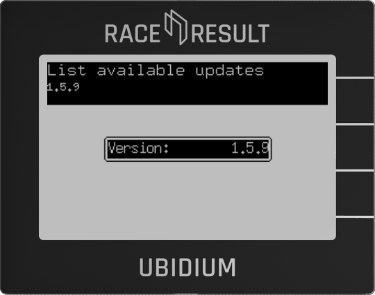
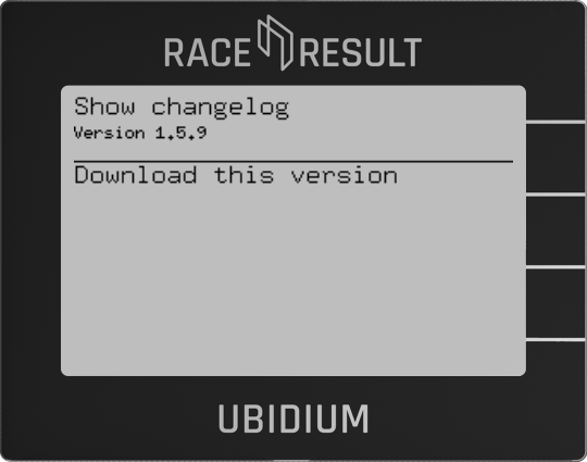
Selecting a version will allow you to review the changelog for that version and start the download.
Download & Install
If a firmware update is available (in auto check mode) then during the shutdown process a selection window will be displayed to either download and install or decline the update.
If the update is declined then the system will prompt again on each subsequent startup and shutdown of the system.
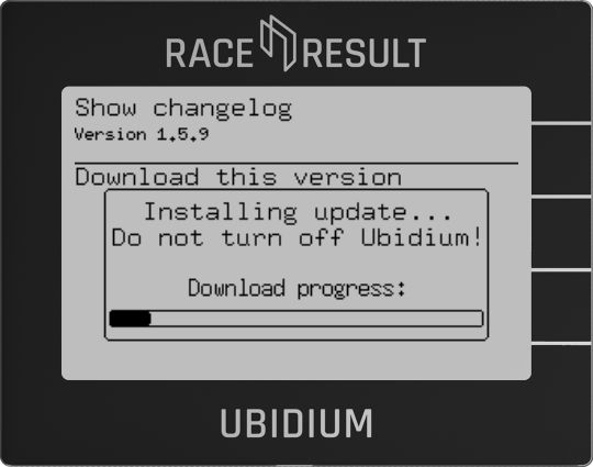
When downloading an update a progress bar is shown, and once the update is downloaded then the Ubidium will show a prompt to shutdown or restart the system, new firmware versions will only be applied on the next restart of the system.
Long-Running Systems
An Ubidium system will automatically be flagged as long-running if it has been switched on and running continuously for a period of more than 10 days.
When in the long-running state then the top bar of the screen will display a notification if an update is available, this will be accompanied by an audible warning every 6 hours if it has been more than 24 hours since the update was found.
The top bar messagewill be supressed if set to manual check mode, however this will still revert to automatic following the same logic as a regular system.
Critical Updates
As of June 2025 - no critical updates have been released for Ubidium.
Critical updates are versions which are considered of the highest importance to ensure systems remain functional. Ubidium systems will always check for critical updates automatically when connected online and these updates will always be downloaded immediately when available.
If a critical update is downloaded then it will be applied in the background and will be available after the next restart, a notification will be shown during the shutdown process stating when this occurs.
For long-running systems an alert will be displayed in the top bar and an audible warning will be given every 15 minutes if the update is not applied with a restart within 1 hour of the initial alert.
Technical Specifications
Bezpečnostné predpisy a nariadenia
Všeobecné bezpečnostné upozornenia
Na udržanie tohto stavu a na zaistenie bezpečnej prevádzky musí používateľ dodržiavať všetky pokyny a upozornenia uvedené v tomto návode na obsluhu.
Pri všetkých vykonávaných prácach sa musia dodržiavať platné miestne a národné bezpečnostné predpisy a pravidlá na prevenciu nehôd.
FCC Vyhlásenie
FCC 15.21
Zmeny alebo úpravy, ktoré nie sú výslovne schválené stranou zodpovednou za zhodu, môžu zrušiť oprávnenie používateľa prevádzkovať zariadenie.
FCC 15.19
Toto zariadenie je v súlade s časťou 15 pravidiel FCC. Prevádzka podlieha týmto dvom podmienkam:
(1) Toto zariadenie nesmie spôsobovať rušenie.
(2) Toto zariadenie musí akceptovať akékoľvek rušenie, vrátane rušenia, ktoré môže spôsobiť nežiaducu činnosť.
IC Vyhlásenie
RSS GEN Issue 5
Toto zariadenie obsahuje licencované vysielače/prijímače, ktoré sú v súlade s Inovatívnym, Vedeckým a Ekonomickým Rozvojom Kanady Canada bez licencie RSS. Prevádzka podlieha týmto dvom podmienkam:
(1) Toto zariadenie nesmie spôsobovať rušenie.
(2) Toto zariadenie musí akceptovať akékoľvek rušenie, vrátane rušenia, ktoré môže spôsobiť nežiaducu činnosť zariadenia.
Cet appareil contient des émetteurs / récepteurs liberés de license conformes aux RSS (RSS) d'Innovation, Sciences and Développement économique Canada. Le fonctionnement est soumis aux deux podmienky suivantes:
(1) Cet appareil ne doit pas reasonr d'interférences.
(2) Cet appareil doit accepter toutes les interférences, y include celles susceptibles de provokatér un fonctionnement indésirable de l'appareil.
Warnings and Cautions
The following alerts are used in this manual:
- WARNINGS alert users of potentially dangerous situations.
- CAUTIONS alert users of potential equipment damage.
Warnings and cautions are indicated by:
- the text WARNING or CAUTION,
- a description explaining the hazard and how to avoid it,
- an icon:

Where to Operate the System
The RACE RESULT Active System uses universal frequencies that can be used globally.
Ground Antenna
The Ubidium Ground Antenna is the most advanced antenna for sports timing, and can only be used with the Ubidium System.
The standard configuration consists of 6 segments of 77cm each, giving a length of 4.6 m / 15 ft, and each segment contains an individual Ubidium Antenna Element.
The ground antenna can be shortened to a minimum of 2 segments (1.5 m / 5 ft) or extended up to a maximum of 30 elements (23 m / 75 ft).
Setup Guidelines
The following guidelines describe the correct setup of your Ubidium Ground Antenna to ensure maximum performance and prevent damage to the components.
Additionally, you should be aware of the setup precautions to further optimise the performance of the system.
Connecting to the System
A single connector is used to connect the Ubidium Ground Antenna to the Expansion Port of the Ubidium System.
It is recommended to only connect or disconnect the Ground Antenna when the Ubidium System is powered off.
To connect the Ground Antenna to the Ubidium System, first open the rubber port cover from the Expansion Port and align the red marker on the outer sleeve of the connector with the red marker on the Expansion Port. This will also align the guide pins on the metal sleeve of the connector.
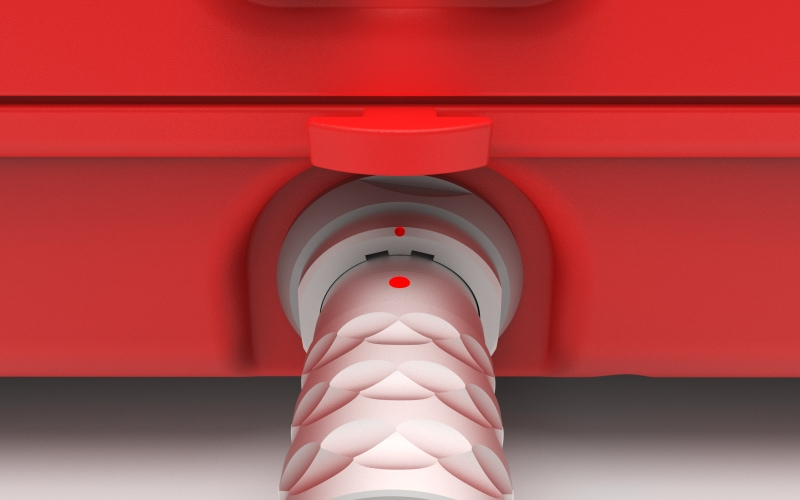
Firmly push the connector in until it clicks in to place, if the connector is correctly inserted it should not be loose inside the Expansion Port.
To remove the Ground Antenna Connector from the system pull on the ridged section of the outer metal sleeve which will release the catch, allowing you to completely remove the connector.
You should always push and pull the connector straight in or out, and at no point should you attempt to twist the connector inside the Expansion Port as this may damage the internal pins.
Components
The Ubidium Ground Antenna is comprised of five key components.
- Black Plastic Base
- Red Plastic Cover
- Ubidium Antenna Element
- Ubidium Connector Cable
- Ubidium Interconnecting Cables
Each component has been carefully designed for maximum performance when used as part of the Ubidium Ground Antenna.
Adding or Removing Segments
The Ubidium Ground Antenna can be shortened down to a minimum of 2 segments (~1.5 meters / ~5 ft) or extended up to 30 segments (~23 meters / ~75.5 ft).
The antenna is designed to be extended or shortened by an even number of segments at a time, the intended splitting points are labelled on the black plastic base of each segment. It is possible to add or remove single segments however this requires additional care and consideration.
Adding or removing segments can be done by opening just 2 individual segments, there is no need to open all the entire length of the antenna.
IMPORTANT: Before adding or removing Antenna Elements - ensure that the Ground Antenna is not connected to an Ubidium System or that the System is shut down.
Opening / Closing The Ground Antenna
To add or remove segments to the Ground Antenna you will need to remove the red plastic covers from the segments at the splitting / joining point.
To remove the covers, lift one edge until the Snap-In buttons release, it should be possible to remove the covers without great force.
Once finished, you must ensure that the covers are correctly fitted to ensure the performance of the system.
To ensure correct fitment, first align the covers and starting on one side push down on the cover to fit the guides joints together then repeat on the opposite side. At the end of each segment it can help to lift the corner of the cover as you are pushing down.
Once the guide joints of both sides are fitted together, start from the middle of the cover and push down moving towards the ends to secure the Snap-In buttons.
Cable Routing
The cabling of the Ubidium Ground Antenna is designed to create 2 unique strands of antennas, to achieve this each interconnecting cable skips one antenna element to connect to the second following element.
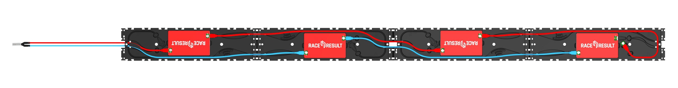
Here the two strands are color-coded red and blue.
The red strand connects to the 1st and 3rd antenna elements and is then in the parking position on the 4th segment.
The blue strand connects to the 2nd and 4th antenna elements, whilst the next blue interconencting cable would be in the parking position of the 5th antenna element to be connected.
Extending the Ground Antenna
To extend the Ubidium Ground Antenna, open the last segment of the existing section and one end of the section to be joined.
Align the 2 sections and connect them using the black plastic hinges, there should be 4 slots to join with hinges.
Remove the interconnecting cables from the parking position on each segment, the coupling joints from each interconnecting cable should be connected to the Antenna Element of the opposite section. Start by gently pushing the plates in to the coupling joint and screw these in by hand to avoid damage to the threads. Once secure then they should be tightened with a screwdriver to ensure they do not come loose.
Only after fitting and securing the coupling joints should you run the cables through the cable channels of the black plastic base, this ensures that there is no additional strain on the coupling joints. The cable channels contain additional slots for slack cable if required.
Shortening the Ground Antenna
To shorten the Ubidium Ground Antenna, open the segments either side of the splitting point.
Start by unscrewing the last coupling joint at the splitting point of the last Antenna Element which will be kept. Similarly unscrew the first coupling joint on the first Antenna Element of the section which is being removed.
The short section of excess cable from each section should be then fitted in to the labelled parking position of the base. This must NOT be looped back and connected to the Antenna Element of the same segment.
To separate the hinges, lift one of the mats to slightly overlap the other and use a slotted screwdriver or similar narrow blunt object to push the hinges out of the joint.
Cover Plugs
One cover plug is included for each Ubidium Ground Antenna Reader Element, this will normally be stored in the parking position, or will be fitted to the final element. The cover plug helps prevent ingress of water and debris in to the coupling joint.
Whilst water will not cause any electrical fault with the system during operation, if dirt and water (particularly salt water or cleaning solutions) are left inside for prolonged periods of time these may cause physical damage to the connectors.
Parking Position
The last interconnecting cable, which will run from the second-last Antenna Element, must not be connected to the last Antenna Element of the same section. This can cause irreparable damage to both the Ubidium System and Antenna Elements.
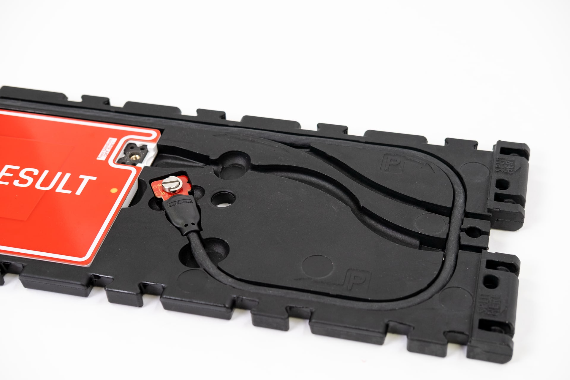
At the intended splitting point of each segment there is an additional cable channel which runs around the perimeter of the segment with an additional cutout for the coupling joint to be slotted in to. This is additionally labelled with "P" to indicate the parking position.
Removing Single Segments
If removing a single segment from the Ubidium Ground Antenna then the joint will not be a designated splitting point and the base will not contain an additional parking position for the excess cable.
In this situation it is recommended that the additional interconnecting cable is removed from the system to prevent damage, it must not be connected to the last Antenna Element.
Maintenance
Cleaning
The Ubidium Ground Antenna can be cleaned with water and non-solvent based cleaning solutions such as car shampoo.
Never use a power-washer on the ground antenna as the high pressure water can damage seals on the coupling joint which may impact the connection of antennas.
Drying
If any element of the ground antenna is submerged in water or exposed to extreme rainfall you should ensure that water does not remain inside the antenna for prolonged storage periods. After any event where you believe water may enter the ground antenna base componenent it is recommended to open the covers to check for water ingress.
If you find water inside the antenna element cutout follow the following steps to prevent damage to sensitive components.
- Unscrew and disconnect both coupling joints from the antenna
- Remove the antenna element and place in a warm, dry room until there is no surface moisture remaining
- Ensure that all plastics and cables are clean and dry, paying particular attention to the coupling joints
- Only once completely dry - replace the antenna element and cables.
Regulatory Information
Human RF Exposure
To comply with exposure requirements of the EU, US, Canada and Japan, this device must be operated at a minimum distance from all persons of at least 30cm/1ft.
Radio Transmitter (FCC Part 15)
This device complies with part 15 of the FCC Rules. Operation is subject to the following two conditions: (1) This device may not cause harmful interference, and (2) this device must accept any interference received, including interference that may cause undesired operation.
Radio Frequency Interference Requirements - FCC
Changes or modifications not expressly approved by the party responsible for compliance could void the user’s authority to operate the equipment.
This equipment has been tested and found to comply with the limits for a Class B digital device, pursuant to part 15 of the FCC Rules. These limits are designed to provide reasonable protection against harmful interference in a residential installation. This equipment generates, uses and can radiate radio frequency energy and, if not installed and used in accordance with the instructions, may cause harmful interference to radio communications. However, there is no guarantee that interference will not occur in a particular installation. If this equipment does cause harmful interference to radio or television reception, which can be determined by turning the equipment off and on, the user is encouraged to try to correct the interference by one or more of the following measures:
Reorient or relocate the receiving antenna. Increase the separation between the equipment and receiver. Connect the equipment into an outlet on a circuit different from that to which the receiver is connected. Consult the dealer or an experienced radio/TV technician for help.
Radio Frequency Interference Requirements - Canada
RSS GEN Issue 5:
This device contains license-exempt transmitter(s)/receiver(s) that comply with Innovation, Science and Economic Development Canada’s license-exempt RSS(s). Operation is subject to the following two conditions:
(1) This device may not cause interference
(2) This device must accept any interference, including interference that may cause undesired operation of the device.
Cet appareil contient des émetteurs / récepteurs exemptés de licence conformes aux RSS (RSS) d'Innovation, Sciences et Développement économique Canada. Le fonctionnement est soumis aux deux conditions suivantes:(1) Cet appareil ne doit pas causer d'interférences(2) Cet appareil doit accepter toutes les interférences, y compris celles susceptibles de provoquer un fonctionnement indésirable de l'appareil
Statement of Compliance - EU/ETSI
race result AG hereby declares that this radio equipment is in compliance with Directives, 2014/53/EU and 2011/65/EU.
Specifications
| Environmental Limits | |
| Outside Air Temperature Range | -20°C...+55°C |
| Element Temperature Range | -20°C...+80°C |
| Humidity (inside segment) | 95% RH, non condensing |
| Temporary Water Ingress (segment) | 24h max, open and dry after use |
| Max. Shock | 10G |
| IP Rating | IPX7 |
Warning: Do not power wash!
| Physical Dimensions & Weight (single segment) | |
| Dimensions | 77 x 35 x 2 cm / 2.5 x 1.1 x 0.07 ft |
| Weight | 3.5 kg |
| Antenna Characteristics | |
| Polarization | Linear along the direction of crossing |
Ground Antenna Detection Data
With each read the system saves some useful information about the passing, understanding this can help to better interpret your data and identify potential problems.
As well as the basic information including the Time and Decoder ID, the following data is recorded for a passive read:
- OrderID - The ID number of the order for which the transponder was printed.
- Hits - The number of times the chip was seen by the decoder during the passing (Not applicable to Track Box Passive data, you should expect lower hits due to the transponder communication protocols).
- RSSI - The strength of the signal received (in dBm) from the passing when the read was recorded.
- A higher value is a stronger detection. For example -42 is better than -60. The best possible value is -35 and the worst value is -85dBm, this is the sensitivity limit.
- Typical values are in the range of -50dBm..-70dBm.
- The RSSI value is the value of the best hit according to your decoder's detection mode.
| Guidelines for detection strength | Hits | RSSI |
| Perfect (could not be better) | 10+ | -35...-55 |
| OK (nothing to worry about) | 3...9 | -55...-65 |
| Not Great (still working, but could be better) | 1...2 | -65...-85 |
| Transponder is in range but not moving* | high value | low value |
*Such as a participant who has already finished watching the race near the finish line whilst still wearing their transponder.
Sprievodca rýchlym spustením
Váš NOVÝ systém Ubidium
Vo vnútri balíka by ste mali nájsť nasledujúce položky:
- Systém Ubidium
- 1 x 98 Wh Ubidium batéria (predinštalovaná)
- 1 x AC nabíjací kábel
- 1 x 13 m slučkový kábel
Ak ste si objednali ďalšie príslušenstvo alebo náhradné diely, môžu byť balené samostatne.
Prehľad Ubidium
Zapnutie Ubidia
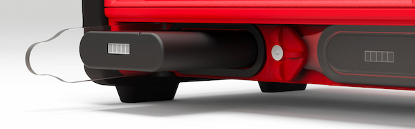
Ubidium má dve priehradky na batérie, ktoré sa nachádzajú na spodnej prednej strane systému, pričom každá priehradka je chránená priehľadným plastovým krytom, vďaka ktorému môžete na integrovanom LCD displeji vždy vidieť aktuálny stav batérií.
Ak chcete otvoriť priehradku na batérie, otočte stredový uzamykací gombík tak, aby bol okraj výrezu zarovnaný s priehradkou, ktorú chcete otvoriť.
Batérie je možné vložiť len v správnej orientácii s drážkou smerom nahor, aby bola zarovnaná so zárezom v otvore priehradky.
Odporúčame vám plne nabiť váš systém Ubidium pomocou dodaného AC nabíjacieho kábla, ktorý je zapojený do AC nabíjacieho portu pod krytom portu. Stav nabíjania nainštalovaných batérií sa zobrazí na displeji, aj keď je systém vypnutý.
Ak chcete systém zapnúť, pevne stlačte a podržte tlačidlo napájania na hlavnej klávesnici, kým sa stavová LED nerozsvieti na zeleno.
Nastavenie času
Ubidium obsahuje vo vnútri vysoko presné hodiny reálneho času, ktoré udržiavajú presný čas, aj keď je systém vypnutý.
Pri spustení Ubidia sa automaticky vyhľadá satelitný signál GPS, aby synchronizoval hodiny s časom GPS, čo poskytuje najpresnejšiu dostupnú synchronizáciu.
Budete sa musieť uistiť, že je v systéme správne nastavené časové pásmo, aby ste mali správny miestny čas, nastavuje sa to prostredníctvom ponuky času, do ktorej sa dostanete stlačením prvého (horného) navigačného tlačidla na pravej strane obrazovky .
Ak chcete zmeniť časové pásmo, vyberte položku ponuky, ktorá zodpovedá časovému pásmu, pomocou navigačných tlačidiel na pravej strane obrazovky.
Rolujte v tejto ponuke nahor a nadol pomocou klávesov so šípkami, aby ste našli správny čas pre vašu polohu a stlačením tlačidla OK ho uložte.
Stlačením tlačidla Späť opustíte všetky otvorené ponuky a vrátite sa na hlavné zobrazenie časovania.
Pripojte sa ku cloudu
Ak plánujete používať Ubidium ako online zariadenie na pripojenie k RACE RESULT 12, budete musieť nakonfigurovať niektoré základné nastavenia na pripojenie systému k vášmu účtu.
Z hlavného displeja časovania otvorte ponuku siete stlačením tretieho navigačného tlačidla na pravej strane obrazovky.
V závislosti od toho, ako sa budete pripájať na internet, možno budete musieť nakonfigurovať nastavenia Ethernet, WiFi alebo Mobile, aby ste vytvorili internetové pripojenie, viac informácií nájdete v Nastavenia siete Ubidium.
Ak používate SIM kartu RACE RESULT, jednoducho ju vložte do portu SIM, ktorý sa nachádza pod chlopňou, a systém ju automaticky nakonfiguruje.
Keď budete online, vyberte položku ponuky Cloud a z nej budete musieť nastaviť Zákaznícke číslo na svoje ID zákazníka RACE RESULT. Ak chcete zmeniť číslo, použite klávesy so šípkou nahor a nadol na zmenu každej číslice a klávesy so šípkou doprava a doľava na výber číslice. Dávajte pozor, ak má vaše ID zákazníka menej ako 6 číslic, prvá číslica by mala byť nastavená na 0. Po dokončení stlačte OK, aby ste hodnotu uložili.
Po nastavení zákazníckeho čísla vyberte možnosť Zapnuté a zmeňte hodnotu na ÁNO. Môžete tiež vynútiť automatické povolenie pri spustení, ak sa tak rozhodnete.
Spustiť meranie času
Ak chcete spustiť meranie času s Ubidiom, stačí k systému pripojiť aktívnu časovaciu slučku alebo Ubidium skladaciu pozemnú anténu.
Obidva sú pripojené k zodpovedajúcim portom na zadnej strane systému, chránené gumeným uzáverom. Upozorňujeme, že banánky v priehradke hlavného portu slúžia na pripojenie impulzných zariadení a nemožno ich použiť na pripojenie aktívnej časovacej slučky.
Pri prevádzke ako aktívny systém tiež nezabudnite otvoriť 2,4 GHz časovaciu anténu z jej slotu a otočte ju tak, aby smerovala vertikálne nahor.