Chip2Go
Chip2Go allows you to program RACE RESULT raw transponders ready to stick directly to bibs.
Raw transponders are fed in to the Chip2Go from a roll, encoded to the required number and fed out ready to easily remove and stick directly to a bib.
The unit features a chip check antenna on the front side to easily check a transponder's code.
Number entry can be achieved through either:
- Touchscreen keypad entry (with optional sequential count-up / count-down)
- USB number pad
- USB barcode scanner
The Chip2Go will only work with RACE RESULT raw transponders, these can be purchased in either single or duo configuration. The machine will automatically recognise these and will program either a single tags or two identical tags according to the roll.
System Setup
Screw in the power cable to the rear of the unit and the Chip2Go will power on automatically.
Chip2Go machines are shipped with a 15v power supply using the same connector as Loop Boxes and Track Boxes. Note that a Loop Box power supply only provides 12v, the Chip2Go will still run but motor speed will be reduced.
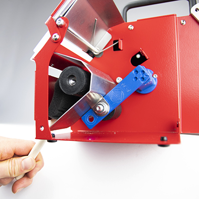
To prepare transponders first raise the mounting arm by pulling the black quick release latch and pulling the arm up until the latch clicks back in to lock the arm in place, the roll then fits on the arm.
Push back the silver brake plate and feed the plastic liner through the upper section of the unit until the first transponder is just visible below the red plate but ensure that the transponder does not cover the white programming antenna. If the programming antenna is already covered by a transponder then this transponder will be fed past the antenna and cannot be used.
On the display push Feed, or manual feed forward, and push the liner in to the slit below the programming antenna until the rollers catch the plastic liner and pull it through. The machine will keep feeding forward until the first transponder is positioned over the progamming antenna.
Once finished you can tear off the excess liner by using the serrated cutter on the lower slit, you should cut the liner here with a transponder still in place as the excess liner is required to feed in to the system at the next start-up.
On the display select Switch Mode and then press manual feed reverse to feed the liner back out of the lower section, if the liner was not cut then it may require multiple presses to fully remove.
The transponders can now be pulled out from the upper secction, the roll removed and the mounting arm returned to it's transport position. To power down the unit simply remove the power supply.
Transponder Number Entry
Chip2Go can encode any number from 1-9,999,999
Transponder Check Antenna
The check antenna on the front side of the Chip2Go can be used to check the chip code of any passive race result transponder.
Simply hold the transponder in front of the check antenna and the chip code will be displayed at the bottom of the display.
If 2 or more transponders of the same code are detected then "Number x 2" will be displayed.
If 2 or more transponders with different codes are detected then "multiple tags" will be displayed.
Firmware Update
The current version is always shown in the top left screen corner.
How to Update
When running firmware is 0.9.9 or newer, the stick with the update must be inserted prior to boot and the machine will ask you whether to update or not. After installing the update, your Chip2Go will reboot and ask you again whether to update or not. Unplug the USB drive now, then abort the message. You may be asked to install 2 further updates, which you can't abort. After installing these updates, your Chip2Go is updated and can be used again.
Note: there must not be more than one firmware file on the USB drive and the drive must be formatted as FAT32.
pre-0.9.9
Download the latest update below and copy this file to a USB drive. Connect the USB drive to the Chip2Go machine and after a short while the LED on the programming antenna will start to flash red and Green
Once the LED changes to just green remove the USB drive and the machine will reboot with the new firmware.
Note: there must not be more than one firmware file on the USB drive.
Changes
-
1.1.4 - Released June 19th, 2024
- show reader busy when tag antenna is inactive
- internal improvements
-
1.1.2
- Fix date encoding bug in order ID for programmed tags
-
1.0.5d
- Handle end of roll properly
- Selectable step width when selecting a USB file
- Barcodes to enable/disable menu (barcodes attached below)
- Fixed error with device licking up if a USB file is not selected
- Feeder timeout race condition fixed
- Improved feed error handling
- Fixed crashing issue
- Other minor improvements
-
1.0.4
- Readjusted check antenna limits after user feedback
-
1.0.2
- Not ready message (new number entered while old tag not picked up) is clearer
- Discard input when not ready for new input
- Improve handling of tag gaps and roll end in single tag mode
- Adjust check antenna power
- Minor improvements
-
1.0.0
- Massive improvement in non-EU and US tag programming reliability
- Race condition during programming could lead to a hanging machine, fixed.
- Pulling tags forward no longer freezes the machine
- Show programmed tag counter and icon for detected usb devices in status bar
- Handling of errors reworked
- USB file reading implemented
- Log file assistant after crashes
- Update of system and UHF firmware must be confirmed, progress is shown for UHF firmware
- Logging reworked, more errors get captured for analysis
- Internal: Log file retention age and size increased
- Further smaller fixes and improvements
-
0.9.5
- Country selection for regulatory compliance
- Improved programming speed and stability
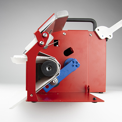
Cleaning instructions
The rubber rollers inside the Chip2Go can collect dust over time which in return can lead to feeding issues. In this case the machine can be easily cleaned. For this purpose we include a brush with every Chip2Go.
To do so put the machine next to the edge of a table and power it up. Remove any tags that may still be in the machine.
Wet the brush slightly with some water or -in case of very greasy/oily dirt- some rubbing alcohol. The brush however must not be soaking wet in ordert o prevent any liquid from getting inside the machine.
Insert the brush into the lower slot as shown in the picture below. Putting it into the upper slot might cause it to be pulled into the machine and damaged in the next step.

Press the „feed“ button on the touchscreen so the rollers start spinning. Push the brush against the rollers and slightly scrub left and right. Repeat the procedure a couple of times depending on the amount of dirt and clean the brush in between.
The machine does not need to be disassembled. The picture is just to show how the brush is to be inserted.
If you need to use the machine immediately after cleaning you can let a paper towel drive through the machine several times to dry the rollers. Do not try to hold the paper towel with your hands since this might cause the towel to rip an get stuck in the machine.
RACE RESULT SIM Card [EU,US,CAN]
RACE RESULT SIM Cards are only for use in RACE RESULT equipment, namely the 5000 series decoder and Track Boxes.
All RACE RESULT Hardware with the latest firmware will automatically configure all the necessary settings (PIN and APN), so no further user interaction is required.
Supported Firmware
- For decoders Firmware version 2.25 or above is required for SIM Cards to function
- For Track Boxes Firmware revision 20938 or above is required
Using older firmware will result in locked cards, which will need to be unlocked against an applicable fee (see Contract for details).
The list of included countries can be found at the bottom of this article (attention: Denmark is not included)
- The SIM cards will work anywhere in the world but are only free of extra charges in the listed supported countries.
Please read the respective contract carefully!
Contract worldwide (except USA & Canada)
Contract USA & Canada
EU & Nordic
- Austria
- Belgium
- Bulgaria
- Croatia
- Cyprus
- Czech
- Republic
- Estonia
- Finland
- France (Guyana, Guadeloupe and Martinique )
- Germany
- Gibraltar
- Great Britain
- Greece
- Holland
- Hungary
- Iceland
- Ireland
- Italy
- Latvia
- Lithuania
- Luxembourg
- Malta
- Montenegro
- Norway
- Poland
- Portugal (Azores and Madeira)
- Réunion
- Romania
- Serbia
- Slovakia
- Slovenia
- Spain (Canary Islands)
- Sweden
- Switzerland
North America
- USA
- Canada
BLE Reader
The RACE RESULT BLE Reader connects to the RACE RESULT EventTools App, it reads RACE RESULT Passive Transponders. The reader is not designed or optimized to be used as a timing device.
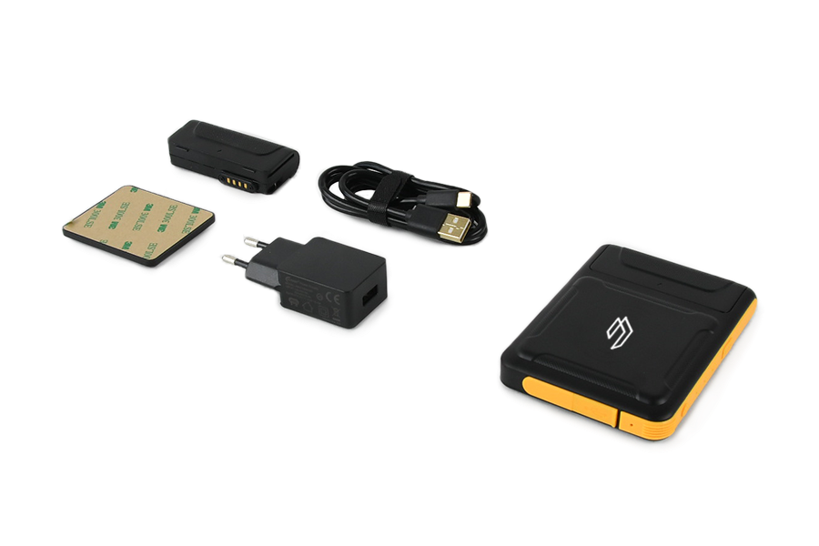
The package includes:
- RACE RESULT BLE Reader
- Spare Battery
- Stick-on magnetic pad
- 5V USB Charger
- USB-A <-> USB-C charging cable.
The battery can be slid out to exchange, if the reader is turned on when the battery is removed it will automatically switch back on when a new battery is fitted.
Buttons & LEDs
The reader has 2 buttons, and 3 LEDs along the top edge.

Buttons
Press and hold the small round power button to switch the device on or off.
At this time the button labelled scan is not used for any operation.
LEDs
Power
- Solid Red - Device is charging
- Solid Green - Battery level above 20%
- Blue - Battery level below 20%
- Off - device is switched off
Bluetooth
- Blue - Bluetooth is connected
- Off - No bluetooth connection
Work
- Flashing Blue - Reading transponders
Technical Specifications
Dimensions & Standards |
|
|---|---|
|
Regulatory Conformity and Standards |
EN60950 (safety) CE, RoHS, FCC |
| Operating Temperature | -20°C to 60°C |
| Dimensions | 108mm x 78mm x 18mm |
| Weight | 200g / 7.05oz |
|
Protection Class |
IP65 -dust tight- |
| Drop Resistance | 1.2m |
Battery |
|
| Capacity | 2000mAh |
| Battery Life |
IDLE - 17h @5dBm - 5h30 @10dBm - 5h15 @15dBm - 5h00 @20dBm - 4h45 @30dBm - 3h00 |
UHF |
|
| Power Output | Adjustable 5dBm - 30dBm |
| Antenna |
Circular Polarized 3dBi |
| Frequency | 865-868MHz / 902-928MHz |
| Expected Read Range |
@5dBm - 0.3m @10dBm - 0.5m @15dBm - 1m @20dBm - 2.5m @30dBm - 6.5m |
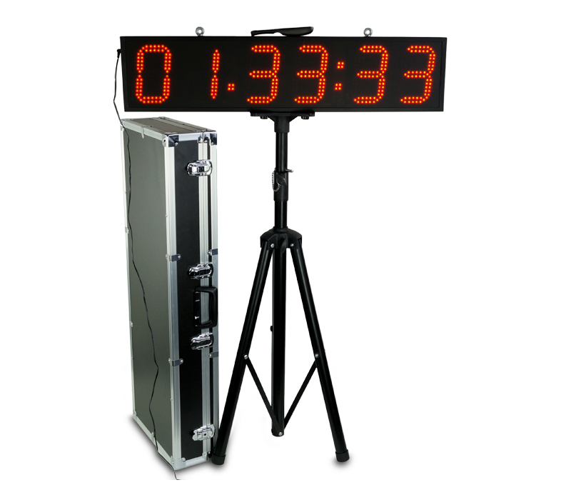
LED Clock
Here you will find documentation about the clock we started selling in early 2018. For the previous model, read the instructions for the LED Clock (old).
The current version of the clock has been further improved in November 2018, with the following improvements and modifications:
- 3.5 mm jack input for start / stop impulses added
- Easier selection and automatic switching between time formats.
- Countdown allows unlimited repetition
- Improved accuracy in all modes
- Unnecessary modes removed.
This manual details the functions of the latest version, with notes for the former version where functions differ. If you have purchased your clock before November 2018 and it does not have a 3.5 mm jack output on the side, you will need to refer to these notes.
The quick start guide gathers all the necessary information for simple use. Read further if you want to find out about the more advanced features of the clock.
Quick Start Guide
1. Set up the clock on the tripod using the thumbscrews and plug in the power supply.
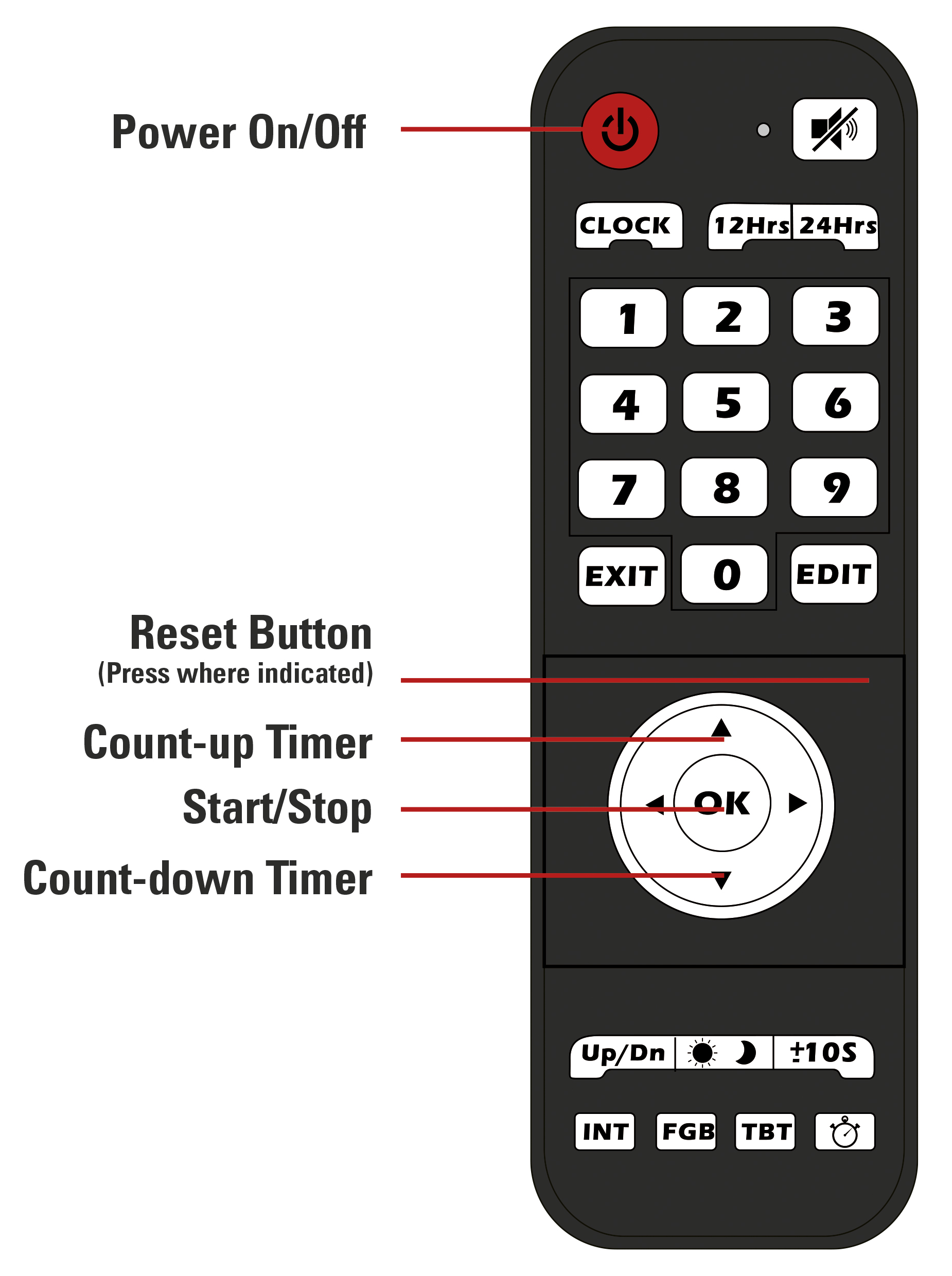
2. Press the red On/Off button of the remote to turn on the clock.
3. Press the Up or the Down Arrow to enter the count up or count down mode.
a) If you want to start with a preset time, press the "Edit" button.
b) Use the number pad to enter the desired time.
c) press "Edit" again to save the time.
4. Press "OK" to start the timer.
5. Press "OK" again to pause the timer.
6. Press the reset button (not labeled) to reset to the preset time.
Remote and Modes
Note: the remote and modes have been modified in November 2018. If you have purchased your clock before then and it does not have a 3.5 mm jack input on the side, please refer to the sub-section for your version below.
Remote:
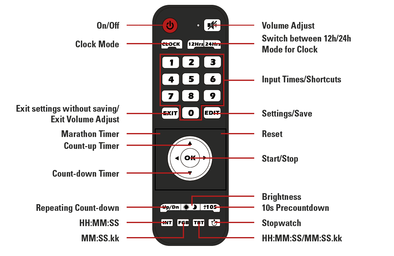
Display Format
During setup the clock always uses the HH:MM:SS format.
For the Count-up and Count-down mode the desired display format can be chosen with the INT, FGB and TBT buttons.
- INT: HH:MM:SS (max 99:59:59)
- FGB: MM:SS.kk (max 99:59.99)
- TBT: automatically switches between the two modes when 1 hour is reached
Input Jack
A 3.5 mm jack input is accessible on the side of the clock, under the connector for the power supply.
This input can be used to collect impulses from any kind of device to start and stop the clock, just as if you were pressing the OK button.
Modes:
Countdown / -up
Function: count down from or up to a specified time
Time format: HH:MM:SS
Accuracy: ±140 ppm
To access and use countdown / - up:
- Press the "Up" button to count up, or the “Down” button to count down
- Use the “Edit” button to set the time to count up or down from
- Enter the desired time using the number pad
- Press “Edit” again to save
- Use the “±10S” button to turn the 10 second pre-countdown on or off
- “-10” stands for no pre-countdown
- “10” stands for 10 second pre-countdown
- Select desired display format using the INT, FGB, or TBT button
- Press “OK” to start/pause the timer
Clock
Function: displays a normal clock in either 12h or 24h format
Time format: HH:MM:SS
Accuracy: ±20 ppm
To access and use the Clock mode:
- Press the “Clock” button
- Use the “12Hrs” and “24Hrs” buttons to switch between 12 and 24-hour format
- Use the “Edit” button to set the clock
- the first digit will start flashing and can be set using the number pad
- when done setting the time press “Edit” again to save the time
Stopwatch
Function: stopwatch
Maximum time: 99:59.99
Time format: MM:SS.kk
Accuracy: ±20 ppm
To access and use the stopwatch:
- Press the stopwatch button to enter Stopwatch mode
- Use the “±10S” button to turn the 10 second pre-countdown on or off
- “-10” stands for no pre-countdown
- “10” stands for 10 second pre-countdown
- Press “OK” to start/pause the stopwatch
- Use the reset (not labeled) button to reset the stopwatch when it is paused
Marathon Timer
Function: stopwatch with internal backup (the time continues to run even if the clock is unplugged)
Time format: HH:MM:SS
Accuracy: ±20 ppm
To access and use the Marathon Timer:
- Press the marathon timer button (not labeled)
- Use the “±10S” button to turn the 10 second pre-countdown on or off
- “-10” stands for no pre-countdown
- “10” stands for 10 second pre-countdown
- Press “OK” to start/pause the stopwatch
- Use the reset (not labeled) button to reset the stopwatch when it is paused
Repeated Countdown
Function: repeats the set count-down timer
Time format: HH:MM:SS
Maximum time: 99:59:59
Accuracy: ±20 ppm
To access and use the Interval Timer:
- Press the “Up/Dn” button to enter interval mode
- Press the “Edit” button
- Enter the desired time using the number pad
- Press “Edit” again to save
- Use the “±10S” button to turn the 10 second pre-countdown on or off
- “-10” stands for no pre-countdown
- “10” stands for 10 second pre-countdown
- Press “OK” to start/pause the timer
Technical specifications
Weatherproof
Input 12V, 2A 
Clock: 88 x 20 x 5 cm; 3,2kg
Case: 101 x 39 x 17,5 cm
Power supply
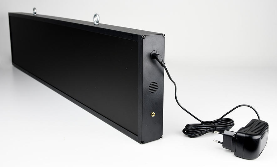
Plug in the LED clock using the included 12V power supply or equivalent. The power supply comes with an adapter for different countries.
5,5mm Barrel connector
You can also use a 12V car battery with and adapter.
The remote uses 2 AAA batteries
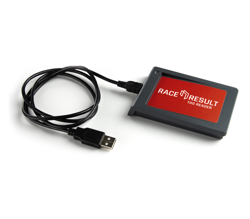
Tag Reader
The Tag Reader reads any RACE RESULT passive transponder and can be used to scan transponders for the following purposes:
- Chip check at packet pickup
- Chip assignment at packet pickup
- Creating chip files
- Result kiosks
It cannot be used for timing!
To use the Tag Reader you should open the TagTool, for this the Local Adapter must not be running.
The TagTool can be used to emulate keystrokes when a chip is read. This way the tag id will be entered in the tool (which can be non RACE RESULT tools as well).
LED Clock (old)
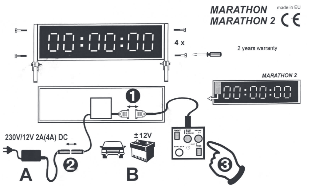
Range:
| Mode | Clock; first character | Meaning |
| D:H:M | d | Day Day : Hour Hour : Minute Minute |
| H:M:S | H | Hour Hour : Minute Minute : Second Second |
| M:S:S/100 | n | Minute Minute : Second Second : 10th 100th |
- Connect the remote as shown above.
- Connect the power as shown above. There are two ways to power the LED clock; either with the included wall-adapter or with the included crocodile clamp and a 12V car battery or other 12V power source.
- Turn on the LED clock by pressing the 'ON/OFF' button and wait until you see the following output: H┌┐:--:--
There are two basic modes of operation; counting up or counting down. It is possible to set the desired resolution (called range below) and start time for both modes.
The first character indicates the range, the second indicates if the clock will count up or down. The range can be changed with the 'RANGE' button
The direction of counting can be set with the UP/DOWN button. ' ┌┐ ' on the second character indicates that the clock will count up, ' ⌴ ' indicates that the clock will count down. - To exit the setup and enter the clock mode press the 'PROG' button.
- If you want to select another start time than 00:00:00, press the 'PROG' button again.
The first digits start flashing and can be adjusted with the '+' and '-' buttons, pressing 'PROG' again advances to the next digit. - Once the desired start time has been selected, start the clock by pressing the 'START - STOP' button.
- To reset the time to the set starting time, press both the '+' and '-' button at the same time.