The Ubidium Ground Antenna is the most advanced antenna for sports timing, and can only be used with the Ubidium System.
The standard configuration consists of 6 segments of 77cm each, giving a length of 4.6 m / 15 ft, and each segment contains an individual Ubidium Antenna Element.
The ground antenna can be shortened to a minimum of 2 segments (1.5 m / 5 ft) or extended up to a maximum of 30 elements (23 m / 75 ft).
Setup Guidelines
The following guidelines describe the correct setup of your Ubidium Ground Antenna to ensure maximum performance and prevent damage to the components.
Additionally, you should be aware of the setup precautions to further optimise the performance of the system.
Unfolding the Ground Antenna
You should start unfolding the antenna from the side on which you will position the Ubidium System.
Stand the antenna vertically with the Connector Cable on the ground, at the edge of your Timing Point next to your Ubidium System.
Depending on the length of your antenna you may find it easier to slightly separate the segments to allow them to stand freely.
Pull the last antenna segment to unfold the antenna across the width of your Timing Point.
Folding the Ground Antenna
Again start at the end of the antenna which is closest to your Ubidium System and ensure the Connector Cable is disconnected from your system.
Starting from the second antenna segment pull the segments towards you to fold the antenna into an accordion at the hinges. It is usually easier to keep the segments standing whilst you fold the additional length of the antenna.
Take care not to lift the segment vertically as this may separate the cover from the base making it harder to fold.
Once all the segments have been folded you can push all of them together to flatten the hinges, and we recommend using the provided strap to secure the segments together.
We recommend folding and storing your Ubidium Ground Antenna with the red covers facing outwards to prevent causing deformations on the edges of the covers.
Setup Precautions
Antenna Length
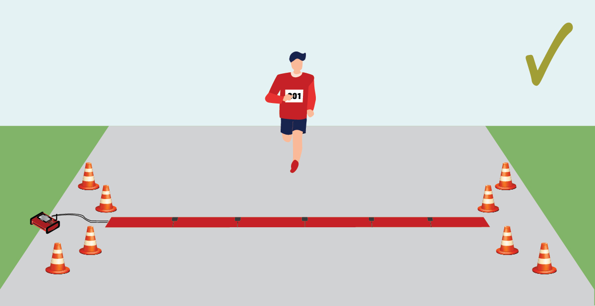
Your Ground Antenna should cover the entire width of your Timing Point to ensure that all participants cross directly over the antennas, it should not be possible for participants to go around the antenna in any way.
If your Timing Point is wider than the available Ground Antenna then you may need to consider setting up barriers to funnel participants across the antenna.
If your Ubidium Ground Antenna is longer than the width of the Timing Point you should split the antenna to remove the unused segments. This will further optimise the performance of the detections since the unused Antenna Elements will not be in operation.
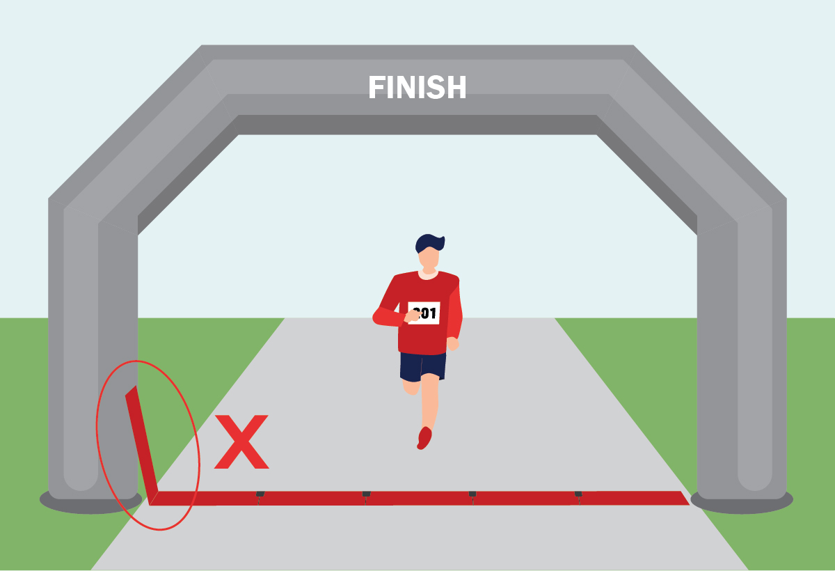
Never fold additional segments vertically to point back across the mat, since multiple elements are activated simultaneously this can cause the detection fields to overlap which may inhibit the performance of the system.
Additional segments should be removed when possible, or can be setup as normal, even laid under other structures, without a negative impact on read rates.
When using Ground Antennas with more than 10 elements where passings in excess of 10,000 participants are expected or those setup on ground with a low friction coefficient, it is recommended to additionally secure the Ground Antenna using a heavy-duty tape on the leading edge.
Using Multiple Systems in Close Proximity
If using multiple systems in the same location, for example using a main and backup timing system at the same Timing Point, then you should ensure a minimum of 5 m / 16 ft between the antennas.

If the detection fields of two separate systems overlap then it can inhibit the performance of both systems.
Protection from External Factors
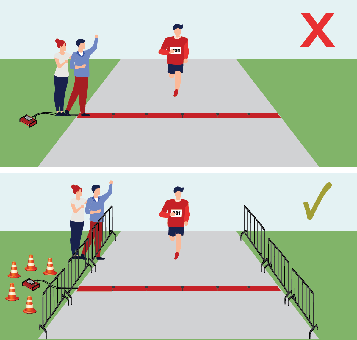
Particularly in busy areas such as the finish you should try to protect your Ground Antenna from unwanted intrusion such as spectators or event staff.
People who are unaware of their surroundings may stand on sensitive components such as the Ubidium System or the Connector Cable which could cause damage to the system or completely break components.
Standing on an Antenna Segment may also cause high reflections on an Antenna Element which will prevent that element from working which may impact your detection performance.
It is also possible that other participants who are standing nearby may cause unwanted detections. Whilst this is normally ignored at a software level it is good practice to try and avoid unwanted detections.
We recommend creating a 1 m / 4 ft buffer around the Ubidium System and Ground Antenna.
Connecting to the System
A single connector is used to connect the Ubidium Ground Antenna to the Expansion Port of the Ubidium System.
It is recommended to only connect or disconnect the Ground Antenna when the Ubidium System is powered off.
To connect the Ground Antenna to the Ubidium System, first open the rubber port cover from the Expansion Port and align the red marker on the outer sleeve of the connector with the red marker on the Expansion Port. This will also align the guide pins on the metal sleeve of the connector.
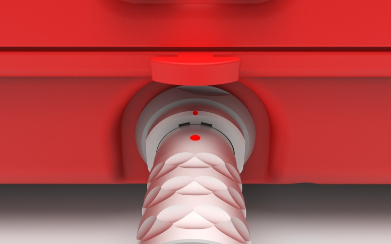
Firmly push the connector in until it clicks in to place, if the connector is correctly inserted it should not be loose inside the Expansion Port.
To remove the Ground Antenna Connector from the system pull on the ridged section of the outer metal sleeve which will release the catch, allowing you to completely remove the connector.
You should always push and pull the connector straight in or out, and at no point should you attempt to twist the connector inside the Expansion Port as this may damage the internal pins.
Components
The Ubidium Ground Antenna is comprised of five key components.
- Black Plastic Base
- Red Plastic Cover
- Ubidium Antenna Element
- Ubidium Connector Cable
- Ubidium Interconnecting Cables
Each component has been carefully designed for maximum performance when used as part of the Ubidium Ground Antenna.
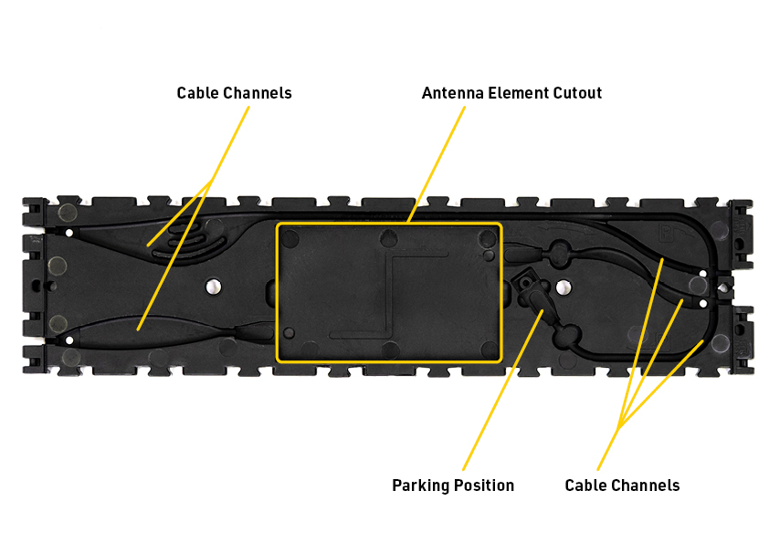
Black Plastic Base
The black plastic base sits on the ground and has cutouts to hold the Ubidium Antenna Elements and cables. It is then covered by the red plastic cover which slots in to place on the side and is secured using the Snap-In Buttons.
The design of the base element is assymetric, one end will additionally be marked as a splitting point and will have a different layout of the internal cable channels. When joining sequential antenna segments the splitting point ends should be joined directly together.
Sequential antenna segments are connected by joining the hinges to the 4 hinge slots on opposing ends of the black plastic base.
Antenna Element Cutout
The Ubidium Antenna Element fits securely in to the central cutout of the black plastic base, the antenna element must be positioned with the RACE RESULT logo facing vertically up. The horizontal orientation of the antenna element does not matter.
Cable Channels.
Each base element contains cable channels to secure and protect the Interconnecting Cables which run between the different antenna segments.
Each end of the base element contains 2 separate open channels, on the splitting end of the element they are in the center whereas on the non-splitting end they will be on the outer edges.
On each end, one cable channel connects to the Antenna Element of this segment, whereas the other will run around the outside edge of the Antenna Element to bypass this segment and connect to the next Antenna Element in that direction.
The channels which run to the Antenna Element of the current segment contain extra wide corners to allow for manufacturing tolerances in the length of the cable.
The antenna bypass channel contains an extra large cutout which then contains three different channels, this is to allow for extra slack to be stored securely inside the segment in the event of substantial difference in cable length.
The antenna bypass channel additionally splits in two distinct channels, one of these is used to connect the cable to the next antenna segment whereas the other is used for the parking position of the cable.
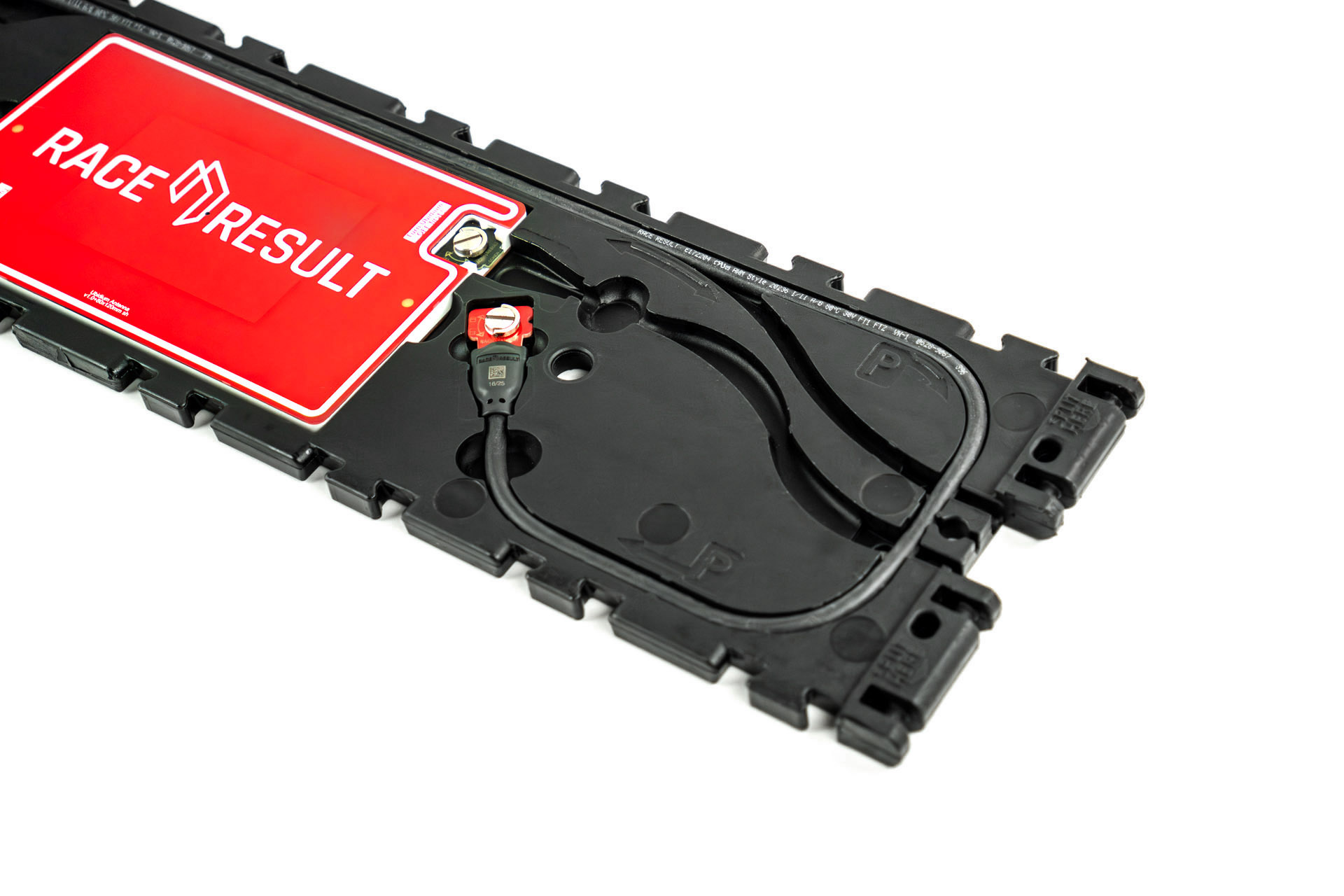
In the last segment of the antenna there will be excess cable, this should be stored in the parking position which runs around the outside perimeter of the base element and is denoted by a P symbol.
The parking position also has a cutout to safely store the coupling joint.
Red Plastic Cover
The red plastic cover fits over the base to protect the internal cables and antenna elements and provide a ramped edge to the mat. The underside of the cover includes the Snap-In Buttons which fit in to the black plastic base, and the guide joints additionally slot in to the base.
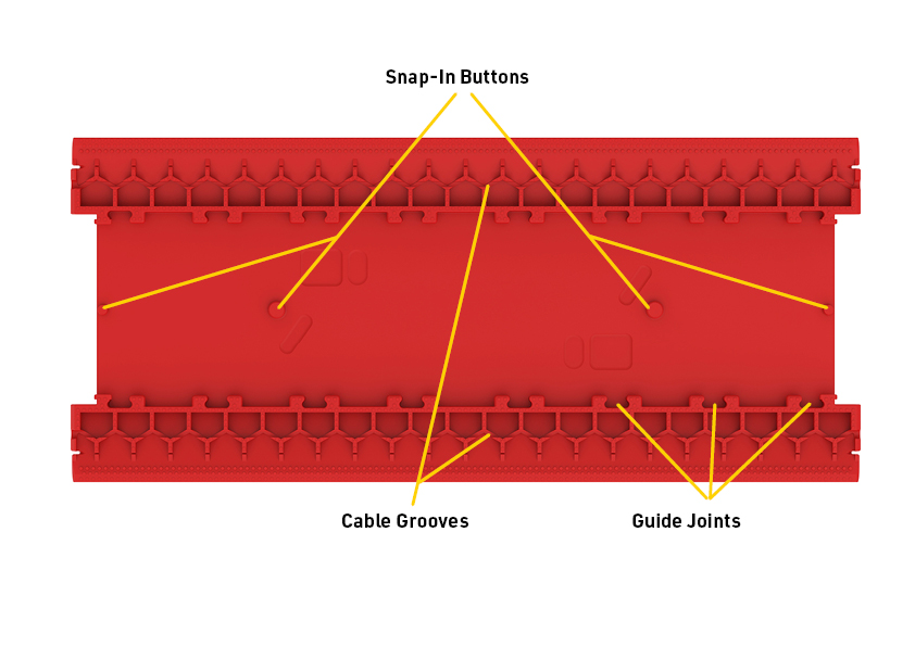
The cover is symmetrical and the orientation of installation does not matter.
The edges of the cover are designed to flex when setup to provide a smooth transition from the ground. Additionally on the underside of the edges is an additional groove which can be used to run additional cables such as power cables or Active Loop Cables.
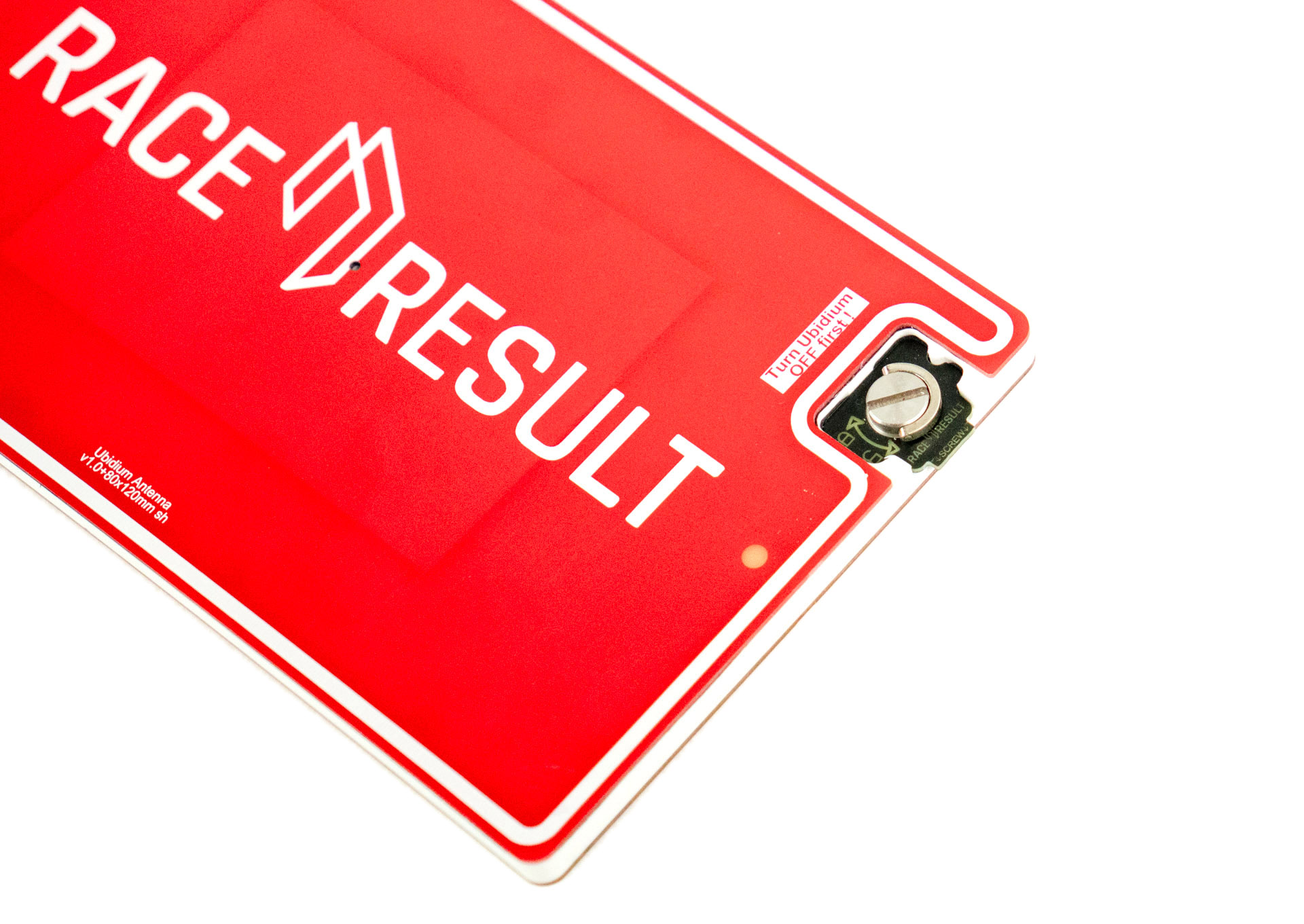
Ubidium Antenna Element
Each antenna segment contains an Ubidium Antenna Element, which is a fully contained UHF Reader and Antenna module.
The antenna element should be installed in the cutout of the black plastic base with the RACE RESULT logo facing upwards. The antenna element can be connected to the Ubidium system through either connection
The element is connected to the system with the coupling joint, it does not matter to which.
The Ubidium Antenna Element will only work with the Ubidium System.
Ubidium Cables
The Ubidium cables are used to carry both power and data, you should not attempt to repair these cables as improper repairs may cause damage to both the system and antenna elements.
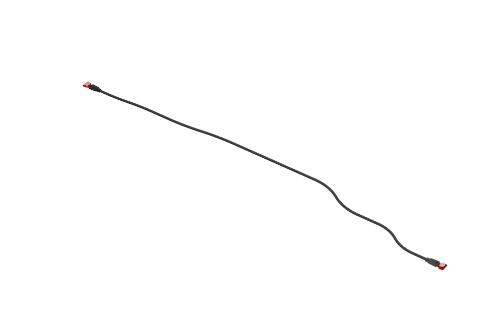
Connector Cable
The connector cable is used to connect the Ubidium Ground Antenna to the system.
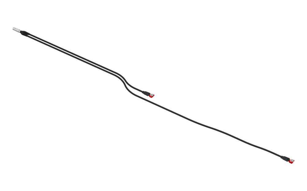
The main connector is plugged in to the Expansion Port of the Ubidium System and then splits in to two individual cables which are used to connect to the first and second Antenna Elements.
Reader Cables
The reader cables are used to connect additional Antenna Elements to the Ground Antenna. The cable ends fit in to the coupling joint or should be stored in the parking position of the base when not in use.
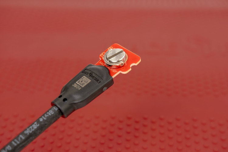
Coupling Joint
The coupling joint is used to connect the cables to the Antenna Element. The central screw should be fully tightened using a flat-head screwdriver in the slot to ensure proper connection.
Adding or Removing Segments
The Ubidium Ground Antenna can be shortened down to a minimum of 2 segments (~1.5 meters / ~5 ft) or extended up to 30 segments (~23 meters / ~75.5 ft).
The antenna is designed to be extended or shortened by an even number of segments at a time, the intended splitting points are labelled on the black plastic base of each segment. It is possible to add or remove single segments however this requires additional care and consideration.
Adding or removing segments can be done by opening just 2 individual segments, there is no need to open all the entire length of the antenna.
IMPORTANT: Before adding or removing Antenna Elements - ensure that the Ground Antenna is not connected to an Ubidium System or that the System is shut down.
Opening / Closing The Ground Antenna
To add or remove segments to the Ground Antenna you will need to remove the red plastic covers from the segments at the splitting / joining point.
To remove the covers, lift one edge until the Snap-In buttons release, it should be possible to remove the covers without great force.
Once finished, you must ensure that the covers are correctly fitted to ensure the performance of the system.
To ensure correct fitment, first align the covers and starting on one side push down on the cover to fit the guides joints together then repeat on the opposite side. At the end of each segment it can help to lift the corner of the cover as you are pushing down.
Once the guide joints of both sides are fitted together, start from the middle of the cover and push down moving towards the ends to secure the Snap-In buttons.
Cable Routing
The cabling of the Ubidium Ground Antenna is designed to create 2 unique strands of antennas, to achieve this each interconnecting cable skips one antenna element to connect to the second following element.
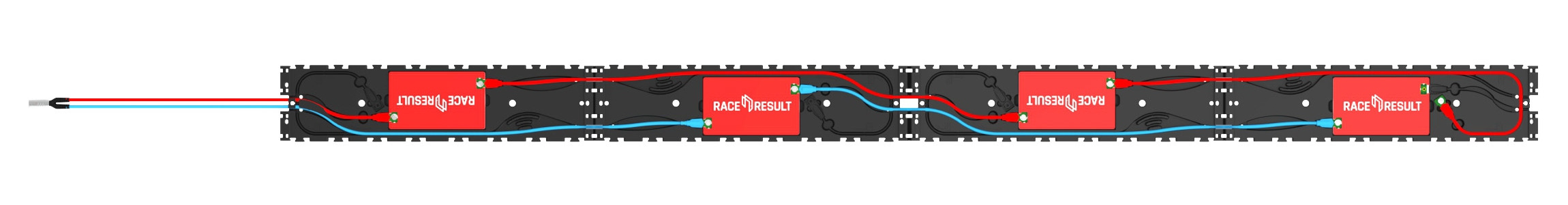
Here the two strands are color-coded red and blue.
The red strand connects to the 1st and 3rd antenna elements and is then in the parking position on the 4th segment.
The blue strand connects to the 2nd and 4th antenna elements, whilst the next blue interconencting cable would be in the parking position of the 5th antenna element to be connected.
Extending the Ground Antenna
To extend the Ubidium Ground Antenna, open the last segment of the existing section and one end of the section to be joined.
Align the 2 sections and connect them using the black plastic hinges, there should be 4 slots to join with hinges.
Remove the interconnecting cables from the parking position on each segment, the coupling joints from each interconnecting cable should be connected to the Antenna Element of the opposite section. Start by gently pushing the plates in to the coupling joint and screw these in by hand to avoid damage to the threads. Once secure then they should be tightened with a screwdriver to ensure they compress the silicone seals and do not come loose.
Only after fitting and securing the coupling joints should you run the cables through the cable channels of the black plastic base, this ensures that there is no additional strain on the coupling joints. The cable channels contain additional slots for slack cable if required.
Shortening the Ground Antenna
To shorten the Ubidium Ground Antenna, open the segments either side of the splitting point.
Start by unscrewing the last coupling joint at the splitting point of the last Antenna Element which will be kept. In some cases you may need to elevate the cable slightly to release the screw. Similarly unscrew the first coupling joint on the first Antenna Element of the section which is being removed.
The short section of excess cable from each section should be then fitted in to the labelled parking position of the base. This must NOT be looped back and connected to the Antenna Element of the same segment.
To separate the hinges, lift one of the mats to slightly overlap the other and use a slotted screwdriver or similar narrow blunt object to push the hinges out of the joint.
Cover Plugs
One cover plug is included for each Ubidium Ground Antenna Reader Element, this will normally be stored in the parking position, or will be fitted to the final element. The cover plug helps prevent ingress of water and debris in to the coupling joint.
Whilst water will not cause any electrical fault with the system during operation, if dirt and water (particularly salt water or cleaning solutions) are left inside for prolonged periods of time these may cause physical damage to the connectors.
Parking Position
The last interconnecting cable, which will run from the second-last Antenna Element, must not be connected to the last Antenna Element of the same section. This can cause irreparable damage to both the Ubidium System and Antenna Elements.
At the intended splitting point of each segment there is an additional cable channel which runs around the perimeter of the segment with an additional cutout for the coupling joint to be slotted in to. This is additionally labelled with "P" to indicate the parking position.
Removing Single Segments
If removing a single segment from the Ubidium Ground Antenna then the joint will not be a designated splitting point and the base will not contain an additional parking position for the excess cable.
In this situation it is recommended that the additional interconnecting cable is removed from the system to prevent damage, it must not be connected to the last Antenna Element.
Maintenance
Cleaning
The Ubidium Ground Antenna can be cleaned with water and non-solvent based cleaning solutions such as car shampoo.
Never use a power-washer on the ground antenna as the high pressure water can damage seals on the coupling joint which may impact the connection of antennas.
Drying
If any element of the ground antenna is submerged in water or exposed to extreme rainfall you should ensure that water does not remain inside the antenna for prolonged storage periods. After any event where you believe water may enter the ground antenna base componenent it is recommended to open the covers to check for water ingress.
If you find water inside the antenna element cutout follow the following steps to prevent damage to sensitive components.
- Unscrew and disconnect both coupling joints from the antenna
- Remove the antenna element and place in a warm, dry room until there is no surface moisture remaining
- Ensure that all plastics and cables are clean and dry, paying particular attention to the coupling joints
- Only once completely dry - replace the antenna element and cables.
Regulatory Information
Human RF Exposure
To comply with exposure requirements of the EU, US, Canada and Japan, this device must be operated at a minimum distance from all persons of at least 30cm/1ft.
Radio Transmitter (FCC Part 15)
This device complies with part 15 of the FCC Rules. Operation is subject to the following two conditions: (1) This device may not cause harmful interference, and (2) this device must accept any interference received, including interference that may cause undesired operation.
Radio Frequency Interference Requirements - FCC
Changes or modifications not expressly approved by the party responsible for compliance could void the user’s authority to operate the equipment.
This equipment has been tested and found to comply with the limits for a Class B digital device, pursuant to part 15 of the FCC Rules. These limits are designed to provide reasonable protection against harmful interference in a residential installation. This equipment generates, uses and can radiate radio frequency energy and, if not installed and used in accordance with the instructions, may cause harmful interference to radio communications. However, there is no guarantee that interference will not occur in a particular installation. If this equipment does cause harmful interference to radio or television reception, which can be determined by turning the equipment off and on, the user is encouraged to try to correct the interference by one or more of the following measures:
Reorient or relocate the receiving antenna. Increase the separation between the equipment and receiver. Connect the equipment into an outlet on a circuit different from that to which the receiver is connected. Consult the dealer or an experienced radio/TV technician for help.
Radio Frequency Interference Requirements - Canada
RSS GEN Issue 5:
This device contains license-exempt transmitter(s)/receiver(s) that comply with Innovation, Science and Economic Development Canada’s license-exempt RSS(s). Operation is subject to the following two conditions:
(1) This device may not cause interference
(2) This device must accept any interference, including interference that may cause undesired operation of the device.
Cet appareil contient des émetteurs / récepteurs exemptés de licence conformes aux RSS (RSS) d'Innovation, Sciences et Développement économique Canada. Le fonctionnement est soumis aux deux conditions suivantes:(1) Cet appareil ne doit pas causer d'interférences(2) Cet appareil doit accepter toutes les interférences, y compris celles susceptibles de provoquer un fonctionnement indésirable de l'appareil
Statement of Compliance - EU/ETSI
race result AG hereby declares that this radio equipment is in compliance with Directives, 2014/53/EU and 2011/65/EU.
Specifications
Ground Antenna Detection Data
With each read the system saves some useful information about the passing, understanding this can help to better interpret your data and identify potential problems.
As well as the basic information including the Time and Decoder ID, the following data is recorded for a passive read:
- OrderID - The ID number of the order for which the transponder was printed.
- Hits - The number of times the chip was seen by the decoder during the passing (Not applicable to Track Box Passive data, you should expect lower hits due to the transponder communication protocols).
- RSSI - The strength of the signal received (in dBm) from the passing when the read was recorded.
- A higher value is a stronger detection. For example -42 is better than -60. The best possible value is -35 and the worst value is -85dBm, this is the sensitivity limit.
- Typical values are in the range of -50dBm..-70dBm.
- The RSSI value is the value of the best hit according to your decoder's detection mode.
| Guidelines for detection strength | Hits | RSSI |
| Perfect (could not be better) | 10+ | -35...-55 |
| OK (nothing to worry about) | 3...9 | -55...-65 |
| Not Great (still working, but could be better) | 1...2 | -65...-85 |
| Transponder is in range but not moving* | high value | low value |
*Such as a participant who has already finished watching the race near the finish line whilst still wearing their transponder.