From the main screen 4 menu icons are displayed, clicking the corresponding navigation key will open the corresponding menu. Clicking the back key from the main screen will also show the label for each menu.

Inside the menu any sub-menus of that item are shown below, sub-menus and menu items can be accessed by clicking the corresponding navigation key.
If an error has occurred then the General Settings icon may display an exclamation mark, this will be cleared when opening the Error Log.
Time Settings
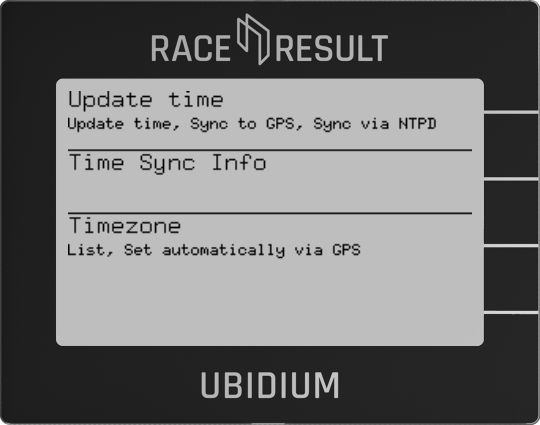
Update Time
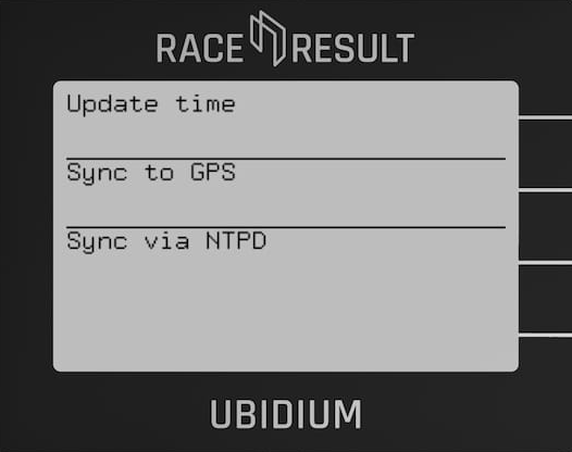
Update Time
Forces the system to find the most accurate available time reference (GPS or NTPD) to set the internal clock.
Sync to GPS
Attempts to scan for GPS satellites in order to obtain an accurate location and sync to GPS time.
Sync to NTPD
Attempts to sync to a web based NTPD service, this is less accurate than GPS time.
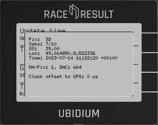
Time Sync Info
When sync'd to GPS the current satellite information is shown, including number of satellites, GPS location, time and clock offset to GPS.
Timezone
Both GPS and NTP time protocols return the current time as a UTC value. To ensure the system is set to the correct time, the time zone must be set accordingly.
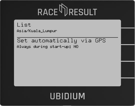
The time zone can be set manually from the list of available time zones, in this list any recently used time zones are displayed at the top of the list and all time zones are then grouped by region or in some cases where individual countries may contain multiple time zones then a group per country.
Alternatively the time zone can be set automatically based on the GPS location of the system, this is only possible when GPS is available, when selecting this option you can also choose to enable this to always set automatically during startup. This option should be used with caution if timing events which may cross timezone borders.
Detection Settings
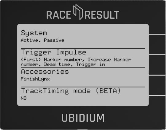
System

Trigger Impulse
Controls how markers are generated when using either the START button or a device connected through the Trigger Port.
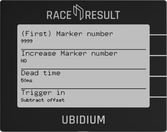
(First) Marker Number
Each marker is generated with a number which is stored as the transponder code in the passing record, this can be up to 7 digits
This is the first number used if Increase Marker Number is set to Yes.
Increase Marker Number
If set to YES then the marker number used will increase with each subsequent marker set.
Dead Time
Dead time sets the minimum time for which the system will wait before accepting a subsequent impulse in milliseconds (default 50ms).
This should only be necessary to adjust if your impulse device creates multiple successive impulses which may cause problems for timing.
Trigger In
If using external inputs to create triggers then an offset can be subtracted from the time the impulse is received. This can be used to offset any delays in transmission of impulses from third-party devices.
Accessories
FinishLynx
When connecting to the FinishLynx LapTime Plugin it may be necessary to set the Sync Source to internal as Ubidium sends the Time of Day for each passing and does not provide times based on a start signal.
TrackTiming Mode (BETA)
Enable or Disable the TrackTiming mode on the Ubidium system.
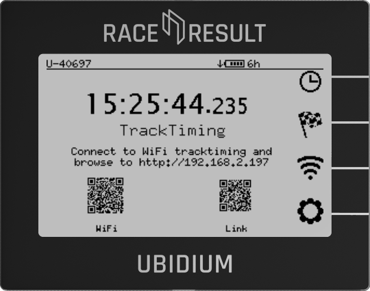
When enabled the menu will automatically exit and return to the main display showing the QR codes to access the system.
Network Settings

Ubidium can be used as part of a local network, or can connect to a remote server to upload data.
There are three different interfaces for networking which can be used in multiple ways.
- LAN / Ethernet
- Wi-Fi (Either as a Client or Access Point)
- Mobile GSM
Ethernet (LAN)
Ubidium contains three ethernet ports which can be used to connect devices on a local network. The ethernet ports of Ubidium are all switched internally and so additional network devices can be connected via Ubidium.
An ethernet connection can also serve to receive an internet connection to enable upload for cloud services or firmware updates.
When using an ethernet connection you must either ensure to use a network router which can then assign IP addresses to each device, or set a static IP address on each device on the network.
It is also possible to connect Ubidium directly to a laptop or computer for timing using an ethernet connection.
For more information on network configuration see our Networking Guide.
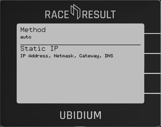
Method
Sets the IP address method to be used, either Auto (DHCP) or Manual (Static IP).
Static IP
Set the IP address, Network Mask, Gateway and DNS Server to be used when using Manual IP address assignment.
Wi-Fi
Ubidium contains an onboard Wi-Fi module which can be used to operate the system as either a Client (connect to an existing network) or Access Point (broadcast a new Wi-Fi network).
When connected as a client the system can connect to the internet via the Wi-Fi connection if available, but the access point mode will not share any internet connection, it will only create a local area network.
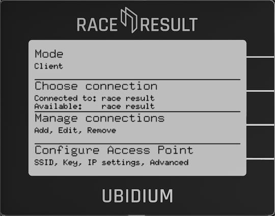
Mode
Switch the Wi-Fi between Client Mode, Access Point or Off.
Choose Connection
When in client mode, select which network to connect to, networks should first be setup using Manage Connections.
The currently connected network, and currently available configured networks will be listed under the menu header.
When in Access Point mode the name of the Access Point will be shown as connected to.
Mobile
Ubidium contains a 4G/LTE module for connecting to the internet via a mobile network, this module supports fallback to 3G/2G where available.
If a SIM card is present then the system will always automatically try to connect to the network regardless of whether or not cloud services are enabled.

The modem has support for both an internal SIM card, provided by RACE RESULT, and a secondary external SIM card port located with the main system Ports.
Note that at this time the internal SIM cannot be used for connecting the system online for timing unless otherwise stated by RACE RESULT.
Cloud
When connected to the internet Ubidium can then connect to the RACE RESULT servers to allow accessing the system remotely for split points or remote timing.
When connected the system will upload current status information and passing information, and can additionally also receive remote commands.
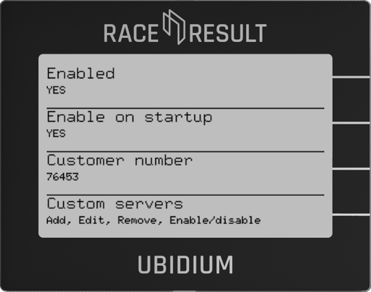
Enabled
Enable or Disable the RACE RESULT Cloud Services.
Enable on Startup
Choose whether the system should automatically attempt to connect to the cloud immediately after startup.
Customer ID
Each system will upload the data linked to a customer ID, this is the numerical ID of your RACE RESULT account. In order to access the system from your account the customer ID field must be set correctly.
General Settings

HW & FW Details

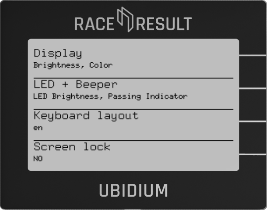
User Interface
Maintenance

Upload Passing Analysis Data
In some cases, RACE RESULT Support may request analysis data from your system, this will be uploaded directly to the RACE RESULT Servers. If you choose to upload this without being requested, please also e-mail support@raceresult.com with further information.
Upload Log Files
Upload the internal system logs directly to RACE RESULT by time frame:
- Since (last) system startup
- From today
- Last 96 hours
- Everything
Status & Error Logging
The firmware will log any errors which occur which can be viewed by opening the menu item.
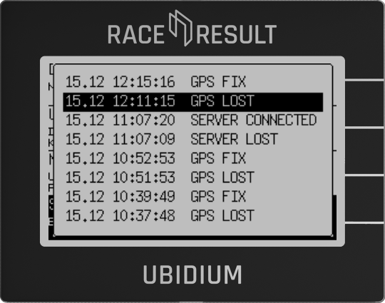
Opening the error log will clear the errors from the main display.