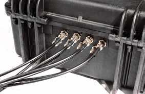
The passive UHF antenna cables connect to the antenna ports on the back of the decoder and are used to detect the RACE RESULT passive transponders/tags. Compared to the active transponders, the passive tags are far less expensive but have less precision and need to be attached (to the race bib, or to an athlete’s ankle, shoe or bicycle) in a certain way for reliable detection.
Antenna Types
RACE RESULT offers two types of antennas for use with passive tags: the ground antenna, used for almost any type of race (running, triathlon, mountain bike, etc.) or the side antennas (available in high gain linear or circular polarizations), which can be used for a flat finish line to avoid the slightly raised profile of the ground antenna or for special applications such as canoe races, skateboard races, etc. Note that the side antennas have two major disadvantages:
- When several athletes pass the timing line they may block the signal from the antenna as the signal does not go through the human body. In other words, the side antenna should only be used for low-density split timing points.
- Since the antenna field is horizontal and does not have a defined end, tags close to the timing line can be detected easily. That is why the side antennas are not recommended for finish line scenarios when athletes can stand close to the system.
As a consequence, the ground antenna is always recommended use where possible and side antennas should only be used when necessary.
Note: side antennas may not be available for sale in all regions.
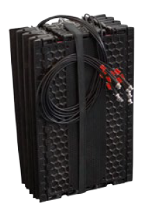
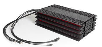
Folding Ground Antenna (5000 series)
RACE RESULT's patented folding ground antenna is the recommended setup for most applications, in particular mass participation running events.

The standard 4.8m ground antenna is comprised of 8 segments of 60cm each, with each element containing an antenna, additional extension kits are available for 6m, or up to 8.4m maximum connected to a single decoder.
By using a ground antenna the distance between antenna and transponder is reduced for all positions and the risk of obstruction between antenna and transponder is also reduced.
Setting up the Ground Antenna
While setting up the ground antenna, please follow these few instructions carefully.
This will ensure correct installation and avoid damage to the antenna and the sensitive coaxial cables.
- Take the antenna out of the box and place it on the ground at the timing location.
- Open the strap.
- Simply unfold the elements of the antenna:
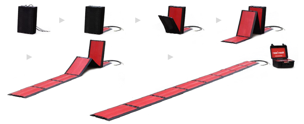
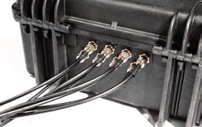
- Connect each antenna cable to the decoder by plugging it in and twisting it clockwise 90 degrees. The cables can be connected in any order.
6 m Extension Kit
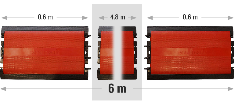
Two empty antenna elements that are attached to either end of the 4.8m ground antenna to extend it by 60cm on either side.
Do this by clipping in the hinge elements; make sure that they do not protrude the surface of the ground antenna.
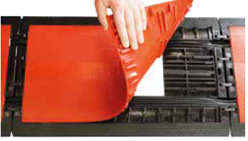
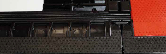
The red top-plate can be lifted up so that the antenna cables can be routed through the corresponding channels, make sure the cables do not cross each other and are laying flat as they might otherwise be damaged.
Afterwards re-attach the red top-plate, some force might be required and we recommend using a rubber mallet.
Caution should be taken when using ankle or shoe mounted transponders with the 6m extension kit since there is no antenna element on the far end of each mat.
8.4 m Extension Kit
The 8.4m Extension kit can be used to extend the width of the ground antenna for wider timing points, the extension kit includes additional mat elements, dummy antennas and extra long cables.
In the 8.4m configuration the mat contains 6 empty mat elements to spread antennas more evenly across the length, for this reason ankle or shoe mounted transponders should not be used when working with mats which have been extended longer than 4.8m.
Follow these instructions carefully to set up the 8m extension kit for the ground antenna. This will ensure correct installation, and avoid damage to the antenna and the coaxial cables.
Required Equipment
|
4.8m Ground Antenna |
|
|
8m Extension Kit |
|
|
Rubber Mallet (not inlcluded) |
|
Instructions
- Unfold the 4.8m ground antenna and the two elements of the 8m extension kit. Place them in the order displayed below and make sure all antenna cables run in the same direction.
- Remove the lids from the ground antenna. Do this by lifting the red panels from the corner of each antenna element. Make sure not to damage the antenna or the coaxial cables.
- Replace the antenna in element 2 and 4 of the ground antenna with one dummy antenna element each. Store the remaining antennas in a safe location. Insert the third dummy element into the empty single element antenna mat (element: 0).
The completed antenna should be setup in the following way: every element marked with an “A” has to contain an antenna, every element marked with a “D” has to contain a dummy element.
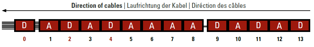
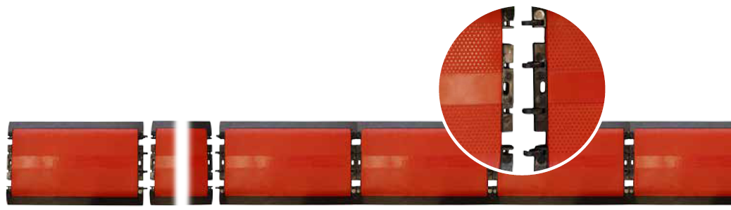
- Connect the ground antenna to the extension kit. Do this by pressing the hinge joints from the five element antenna mat into the corresponding spaces of the ground antenna. Repeat this to connect the single element antenna mat to the ground antenna. You can use a rubber mallet to simplify this step.
- Place both antenna cables from the five element antenna mat into the channels of the ground antenna and the single element antenna mat. Afterwards place the six antenna cables from the 4,8m ground antenna into the channels of the single element antenna mat.
- Close the lids of all open antenna mats. Ensure that the cables do not cross over within the element. Work in the direction of the cables - starting at element 8, working through to element 0.
Then press or step on the lids in the following order: first at the center of the short sides, next on the corners and finally on the edges of the element. Never hit in the middle of the lid. Use a rubber mallet to simplify this step.
- Connect each antenna cable to the decoder by plugging it in and twisting it clockwise 90 degrees. The cables can be connected in any order.
- Perform a brief function test. Switch on the decoder and validate that the antenna is working properly, e.g. by using a Test Transponder.
Splitting a 4.8 m antenna to 2 x 2.4 m
To cover two separate lanes with the same timing line, or to create a main and backup timing line with one decoder, you may want to split your 4.8 m antenna into two parts of 2.4 m.
Note that we do not recommend using a split antenna as a main and backup line on a timing point that requires a high level of precision.
Here is why: a decoder connected to two consecutive timing lines should see two peaks in signal strength for each participant, but it is impossible to define a reaction time that would ensure that these two peaks are systematically treated as two separate detections, regardless of the speed of the participant and the environment. If the second peak is detected before the reaction time has elapsed, the decoder will take the highest peak to record the time, which could be on either timing line.
A single detection line per decoder is the only way to guarantee precision at your finish line. If you are using only one chip per bib, then it is best to use two decoders with one detection line each at the finish. More information about Combining multiple ground antennas and decoders.
A split antenna is however perfect for timing points where you need to improve the read rate and do not need high precision, for example at the swim exit of a triathlon.
You can find more information about the way times are calculated by our passive system in this article about Detection Setup
When connecting 2 lines of mats to a single decoder it is recommended to keep the maximum distance between the 2 mats to a maximum of around 2 meters. When spreading the mats further apart you create 2 distinct read zones each of which is only active half the time due to the multiplexing of the decoder.
The following video shows how to separate your ground antenna.
Combining multiple ground antennas and decoders
When setting up multiple timing lines using ground antennas, there is some key information to understand.
- The most common reason for missed detections is participants directly blocking the transponder with their arm when stopping a GPS watch or device. Spacing lines apart increases the chance that the chip will not be blocked.
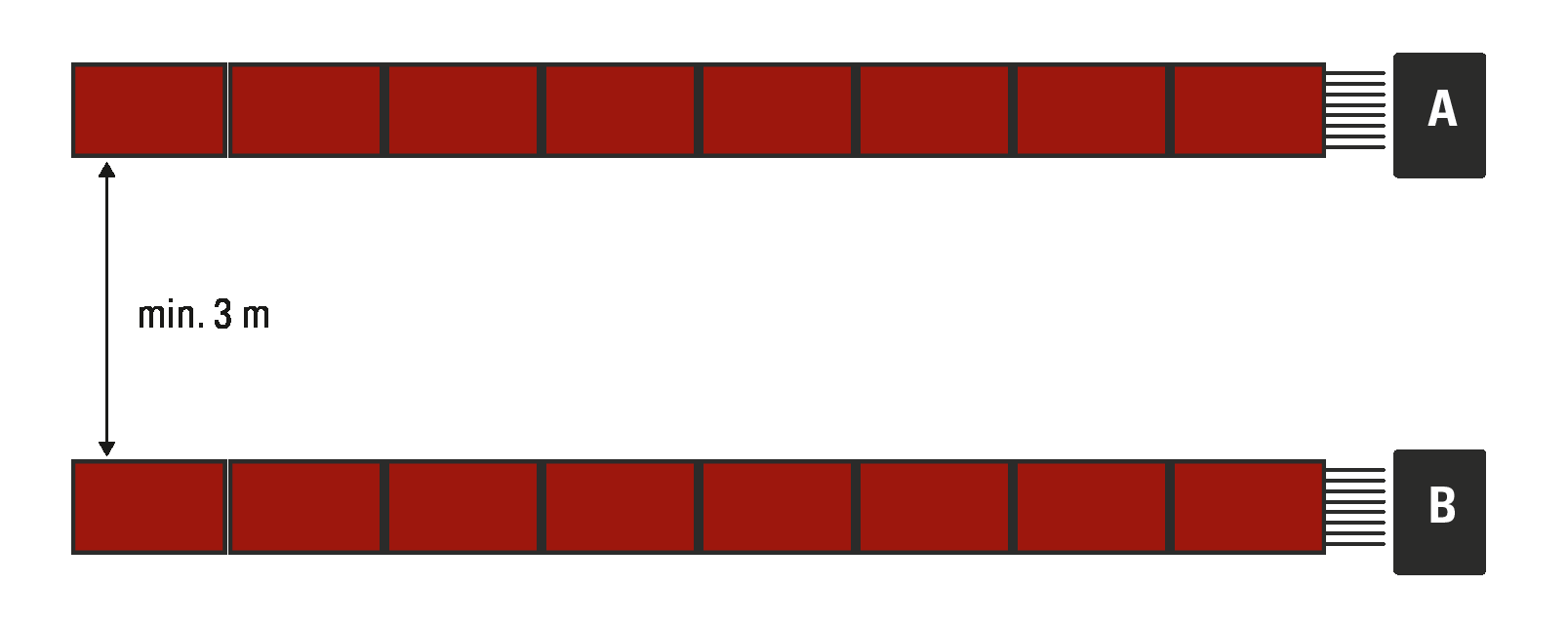
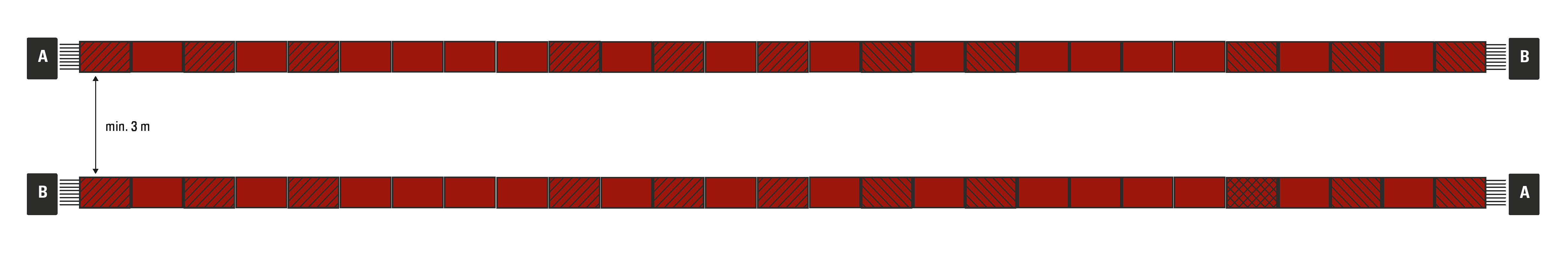
- Transponders cannot communicate with 2 different readers at the same time, so a minimum distance of 3 m (recommended 5 m) should be kept between detection lines placed one after the other (e.g. a main line and a backup line). When setting up two systems next to one another to cover a wider detection line, it is better to have a dummy element in the middle, not sending any signal. For this, you can either add one dummy element from an extension, or simply not connect the last element of one of the antennas.
- A decoder will switch through all the connected antennas approximately 25 times per second, at any given time only one antenna is active, using a single decoder is therefore technically reducing the read time on each line.
- If using EU frequency decoders, it is necessary to set the Channel for each decoder accordingly, by default this is set to Auto. There are 2 options "A" and "B", these should alternate between decoders to maximize read rates. This should be set back to Auto when the decoder is used alone.
Use cases:
Two decoders, main and backup:
- Set up the antennas at least 3 meters (recommended 5 meters) apart
- If operating on EU frequencies, make sure to set one decoder to frequency A, the other to frequency B.
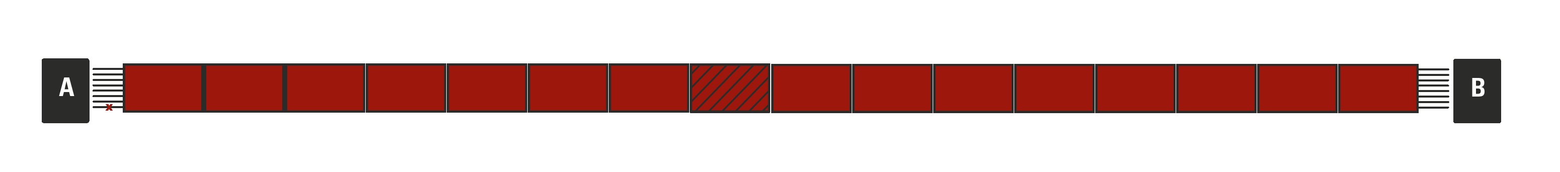
Two decoders side-by-side to cover a wider detection line:
- Use hinges to join antennas in the middle
- Make sure to have one element in the middle not sending any signal. For this, you can either insert one dummy element from an extension, or simply not connect the last antenna on one of the two decoders (connect cables 1-7 of the antenna, leave cable number 8 not connected).
- If operating on EU frequencies, make sure to set one decoder to frequency A, the other to frequency B.
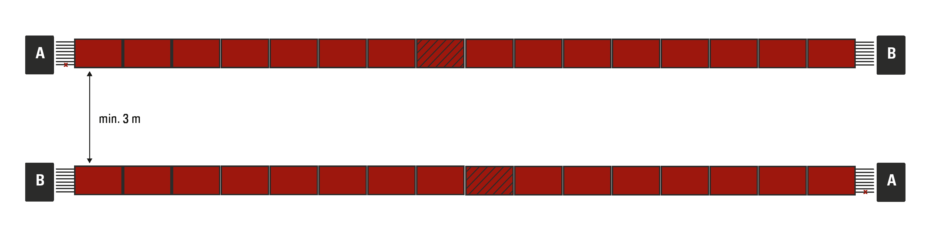
4 decoders, main and backup line, side-by-side:
- Observe the same precautions as in the examples above
- If operating on EU frequencies, alternate frequencies A and B on your decoders as shown below
4 decoders with extension, 16 m main and back up line:
- Remove one dummy element in the middle of each 16 m line, so as not to have 2 dummies side by side. On each line, one side should have 13 elements, the other 14. With 27 elements, you can cover up to 16.2 m.
- Otherwise, observe the same precautions as above.
Technical Specifications
Weight & Pack-Size |
||
| Weight | Pack-Size | |
| 4.8 m Antenna | 25.3 kg | 60 x 40 x 20 cm |
| Antenna Extension Kit | 6.2 kg | 60 x 37 x 5 cm |
| Antenna Height | 2 cm | |
| Antenna Depth | 29 cm | |
Specification |
||
| Antenna Frequency | 865-868MHz (EU), 903-927MHz (US), 920-925MHz (AUS) | |
| TX Power | 33dBm max | |
| Track Width: | 4.8 meters 6 meters with 6m Extension Kit, 8.4 meters with 8m Extension Kit |
|
| Read Range [1] | 4 meters | |
| Detection Rate Read Rate |
> 99.8% [2] > 2,500 tags/min |
|
| Maximum Transponder Speed [3] | 40 km/h, 25 mph | |
| Timing Accuracy [4] | 200 ms | |
[1] Transponders are detected multiple times while crossing the antenna. The detection with the highest signal strength - right above the antenna - is used for timing.
[2] With transponders attached correctly.
[3] Higher speeds are possible, detection rate may be lower.
[4] Use GPS time to get the most accurate results.
High Gain UHF Antenna for Special Applications
The High Gain UHF Antenna is designed for special applications where a ground antenna may not be suitable or possible to use. We always recommend using our Ground Antenna where possible, since all antennas require line of sight between the antenna and transponder.
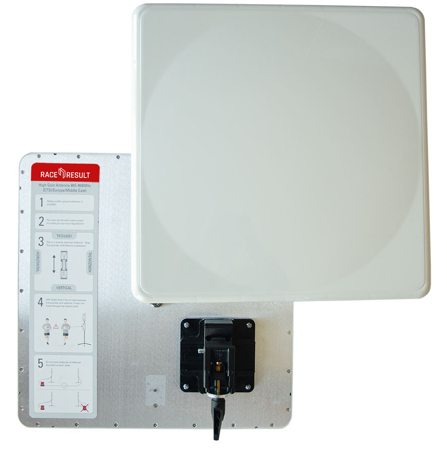
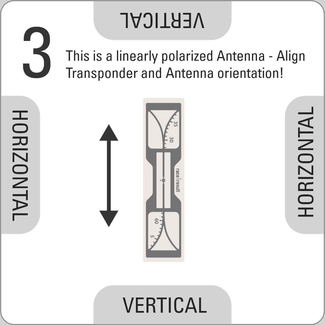
Using the included clamp and mount, antennas can be attached to a variety of structures and easily rotated to match the required orientation of antenna to the transponder. The antenna is linearly polarized but can work with either vertically or horizontally orientated transponders, to do so you must ensure that the antenna is correctly orientated to ensure optimal read rates.
To ensure the antenna is correctly orientated the label on the back acts as a guide, the transponder pictured on the label should match the orientation of the transponders which you will be reading, there is also text to help ensure that this can be communicated.
To rotate the antenna press the silver quick release pin on the clamp, remove the antenna from the clamp and rotate accordingly then push the brass knuckle back in to the clamp, aligning the clamp with the guide on the antenna.
Setup Guidelines
- When setting up antennas facing each other they must be connected to the same decoder, do not use different decoders when antennas are facing each other.
- For optimal precision we recommend a setup with 2 antennas on each side, mounted one above the other, with both pairs facing each other, and all four antennas connected to the same decoder using 12m cables for the antennas positioned further away from the decoder.
- When using main and backup systems the minimum gap between each setup should be equal to the width of the timing point. A chip in the middle of the 2 should not be detected by either system to ensure there is no conflict between antennas.
- When using main and backup systems the decoders should be positioned on opposite sides of the course (e.g., main decoder on the left of the course, and backup decoder on the right of the course), this ensures maximum detection strength on each side.
- For maximum read rate you can offset antennas on the same side slightly (e.g. 80° and 100° to the road), this maximises the width of the read field.
- When using multiple antennas with a large gap between them, you need to consider the decoder's Detection Setup settings to ensure optimal accuracy. If a transponder travels at high speed and passes both antennas within the reaction time then the time may be taken from the later antenna if the RSSI is stronger. This can be avoided by reducing the reaction time or using multiple decoders spaced apart sufficiently.
Warning: As this is a 13dBi High Gain antenna you will need to set your decoder power accordingly to comply with local regulations.
Connecting Antennas to the Decoder
For maximum performance the antennas need to be connected before turning on the decoder since it performs a fine tuning while booting. When connecting the antennas after turning on the decoder, the system still works but the performance may be slightly reduced.
Antenna Indicator on the Display
The display will show a block (█ - or A/B if one of these frequencies has been selected, see above) for an antenna port if an antenna is connected, or an X if no antenna is connected or if the antenna is broken:
| N | o | P | a | s | s | i | n | g | s | T | i | m | e | : | 0 | 0 | : | 0 | 0 | : | 0 | 0 | . | 0 | 0 | 0 | 4 | 5 | 6 | 2 | |||||||||
| F | i | l | e | N | o | : | 0 | I | P | : | 1 | 9 | 2 | . | 1 | 6 | 8 | . | 1 | . | 2 | 0 | 0 | 2 | 5 | 2 | 3 | 3 | |||||||||||
| U | p | l | o | a | d | : | o | f | f | A | n | t | e | n | n | a | s | : | █ | X | █ | █ | █ | █ | █ | █ | 2 | 6 | 6 | ||||||||||
| U | S | B | : | n | / | a | B | a | t | t | e | r | y | : | █ | █ | █ | █ | █ | █ | █ | █ | 2 | 1 | 1 | 1 |
The left-to-right order of the antenna indicators mirrors the left-to-right order of the ports on the back (or right-to-left when looking from the rear).
When an antenna detects a tag, the symbol will switch to an O for the duration of one second.
| N | o | P | a | s | s | i | n | g | s | T | i | m | e | : | 0 | 0 | : | 0 | 0 | : | 0 | 0 | . | 0 | 0 | 0 | 4 | 5 | 6 | 2 | |||||||||
| F | i | l | e | N | o | : | 0 | I | P | : | 1 | 9 | 2 | . | 1 | 6 | 8 | . | 1 | . | 2 | 0 | 0 | 2 | 5 | 2 | 3 | 3 | |||||||||||
| U | p | l | o | a | d | : | o | f | f | A | n | t | e | n | n | a | s | : | █ | █ | 0 | █ | 0 | 0 | █ | █ | 2 | 6 | 6 | ||||||||||
| U | S | B | : | n | / | a | B | a | t | t | e | r | y | : | █ | █ | █ | █ | █ | █ | █ | █ | 2 | 1 | 1 | 1 |
In Europe, UHF has a very small bandwidth, which means two or more systems at one timing point can interfere with each other. When using several European RACE RESULT Systems at the same timing point, different frequencies should be set in order to reduce interferences. In the Frequency menu, you can chose between an Auto mode, frequency A and frequency B. Please see recommended frequency settings in the graphics below.
Frequency Setup (EU Systems Only)

Passive Antenna FAQs
RACE RESULT Ground Antenna With Third Party Readers
Our ground antennas can be used with any UHF RFID reader, but some aditional precuations should be taken when ordering.
Antenna Frequency
We produce antennas specifically according to the UHF frequency range used in your region (EU: 865-867Mhz, US: 902-928Mhz), make sure you order the correct antennas for your reader / region.
Antenna Connection
Our antennas are normally produced with BNC connections, your system may have different connections such as TP-TNC.
If you require antennas produced with any connection type other than BNC then these can be made for 100EUR per set.
We do not recommend using adapters as there will be significant detection loss with these.
Some readers expect an antenna with a 10k resistor for automatic antenna detection, this is included in our design.
Chip Orientation
Our antenna is optimised for a linearly polarised chip, this is different from some other systems. (Our chips should be stuck vertically on bibs). You must ensure to use chips which are correctly polarised and for this reason it may not be possible to mix antennas from other systems with ours in the same event.
DISCLAIMER
When using the RACE RESULT ground antenna with third party readers we will not guarantee the same precision or read rates as when used with a race result decoder since other readers may not use such advanced detection algorithms.
Extra Wide Timing Points
It is possible to have a single timing point up to 16m widing using the RACE RESULT ground antennas, when placing one decoder on each side. You can match any combination of mat lengths (4.8m, 6m, 8.4m) to create extra wide timing points.
If joining multiple mats in the middle with 2 different decoders you should ensure to leave at least 1 blank, or disconnected, antenna element in the middle section where the 2 mats join, this is because a transponder can only communicate with 1 decoder at any one time so this reduces the cross reads which occur.
If using an EU decoder then it is also necessary to set the UHF Channels to A/B for each system to reduce the interference between the 2 systems.
Find more information about this in this article about Combining multiple ground antennas and decoders
Side Antenna Use
RACE RESULT Side Antennas or High Gain UHF Antennas can be an alternative to our ground antenna when conditions may not be suitable to use a ground antenna but there are some additional precautions which should be made when using these setups. In most setups the High Gain UHF Antennas offer better performance that the Side Antennas.
Setup
A side antenna set includes 2 tripods each with 2 antennas, 2 x 2m cables and 2 x 10m cables, they are intended to be setup with one tripod on each side of the detection area, connected to a single decoder.
High Gain UHF Antennas and cables are sold separately allowing for more flexible setups. The antenna includes the unique clamping device for securing the antenna to posts or tripods.
You must NOT connect antennas to multiple decoders when facing each other, this will result in extreme reduction of read rates as transponders cannot communicate with 2 different decoders simultaneously.
To achieve maximum detection rates then you should ensure that the detection range is minimised as much as possible, we advise a maximum 4m timing point width when using side antennas.
Detections
UHF RFID relies on clear line of sight between the antenna and transponder, for this reason when used at dense timing points detection rates may be reduced since there may be no clear line of sight from antennas to participants in the middle of a pack.
As the width of the UHF field is much wider with side antennas the accuracy of times will also be reduced, therefore side antennas are not suitable where precise timing is required such as finish lines.
With free space it can be possible to record detections distances up to 20m however the side antennas are greatly influenced by the environment around them. Depending on the transponder, side antennas can read everywhere around the antenna (even behind them). Important is the gain of the antenna.
Recommended Uses
Side antennas / High Gain Antennas can used for the following applications:
- Mass participation cycling events using Helmet Tags, Seat Post Tags or Bike Plates
- Running event split at low density point
- Running event announcer point (This may produce additional data from other participants standing nearby)
Other Uses
Due to the design of side antennas on their tripod we do not advise using them in the following scenrios.
- Running event dense timing points such as Start / Finish lines
- Running events using Shoe Transponders
- Events using HuTags