New Decoder Setup
When receiving a new RACE RESULT decoder you will want to take some steps to configure it to your required settings. Below are some of the key settings to consider when setting up a new decoder.
Time Zone
The decoder is able to sync to GPS time using the onboard module which is the recommended method for syncing time during a race. You will need to set the time zone to your local time zone to ensure the GPS time is correct.
To do this the decoder must be in Test mode, open the Menu and navigate to Time -> Configure GPS Time
The default Time Zone will be Europe / Amsterdam, to change this highlight the time zone, press OK and use the left/right arrows to change the time zone.
IP Address
By default the decoder will use DHCP to receive an IP address automatically from the network. If using a network with fixed IP ranges or connecting directly from your decoder to a laptop with no network then you may need to set a static IP address.
The IP address can be configured in the network menu, you will need an understanding of Managing IP Configuration.
Upload
If using the upload from the decoder to access the system online you will need to ensure the upload is correctly configured for your account.
Open the menu and navigate to Upload, here you will need to set the Customer ID to your RACE RESULT customer ID which you will use to login to RACE RESULT 12. The decoder will only be available to this account.
If using the internal GSM module with a SIM card then you may need to check the APN settings, by default the decoder will use AUTO APN settings, which work for most major providers worldwide, however some may require custom settings, in particular if using a SIM PIN.
APN settings can only be configured through the decoder browser interface which can be accessed in your web browser by entering the IP address of the decoder when connected via a local network.
Startup Options
To save time and simplify setup, particularly for remote splits, it is possible to set the decoder to automatically set / enable key settings during the startup. You can set all, none or any combination of the following settings:
- Set GPS Time
- Activate Timing Mode
- Enable Upload
To enable the startup options open the Menu and navigate to System, highlight the startup options and press OK to cycle through the options.
Marker
If using the decoder to set a marker (time stamp) then you will need to enable the marker, since this is not enabled by default.
To enable markers, open the menu and navigate to Trigger Impulse, highlight Marker (off) and press OK to cycle the menu to enable a marker number. The default marker will use the number 99999, press OK again to change this number.
Configure GPS time on a 5000 series decoder
This article will teach you how to configure the Time Zone setting on your decoder and then sync your decoder to GPS time.
- NOTE: The MENU button is in the center. The OK button is on the lower right.
- Navigate to Menu > Time > Configure GPS time.
- Use the left and right arrow keys to select your correct time zone. Press OK to confirm.
- Press Cancel once to navigate back to the previous menu (Time menu).
- Select Set GPS Time and click OK. The decoder will then start searching for GPS satellites
- Wait for the decoder to connect to GPS.
- Once the decoder finds GPS, you will see a clock at the top of the screen. Make sure this is showing the correct time of day. If not, double-check your Time Zone and sync GPS time again.
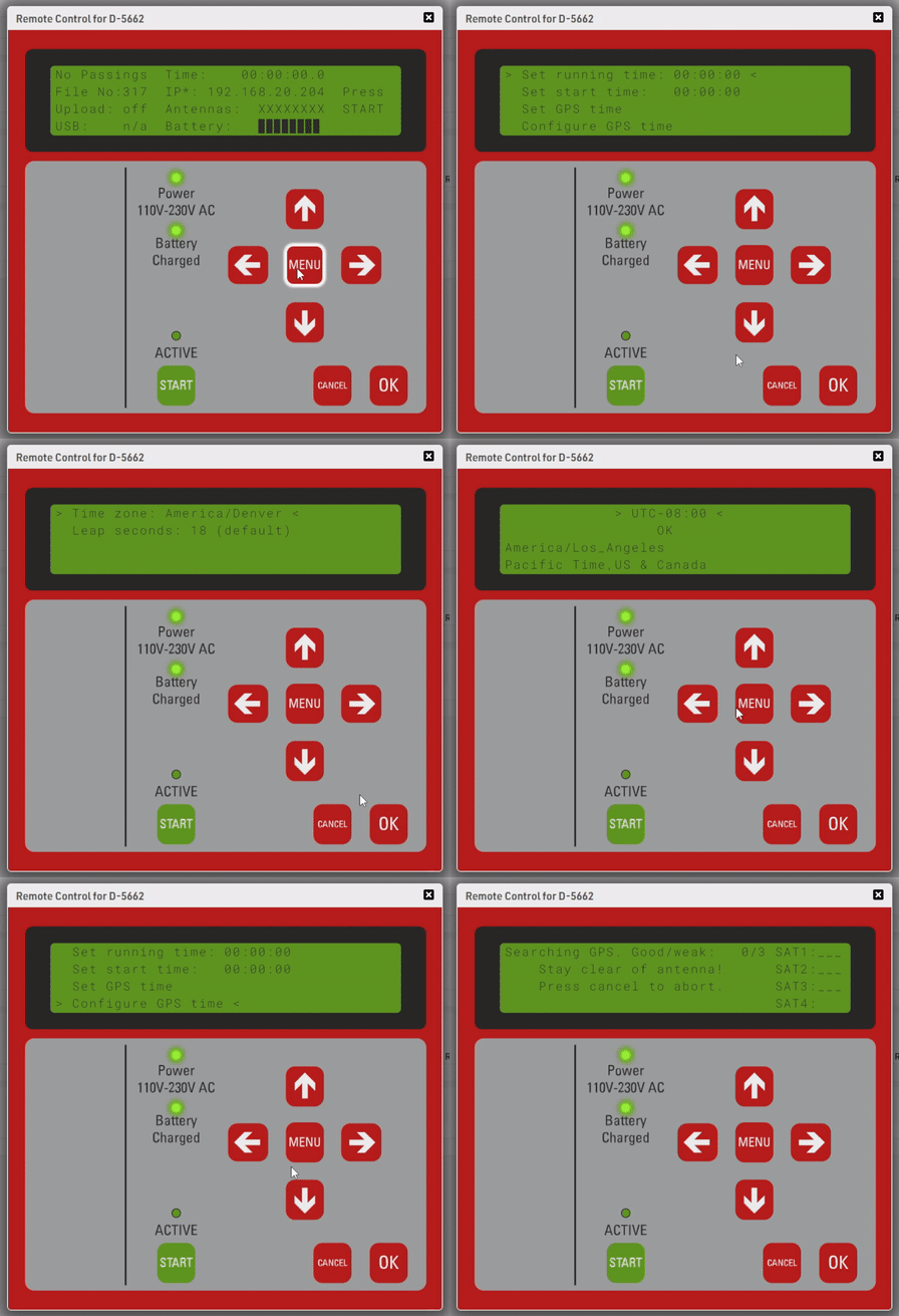
The Time Zone setting is saved on your decoder. It will not need to be set again unless you change it or move to a different time zone.
You will need to sync GPS time each time the decoder turns on. If you want to automate this, you need to change the Startup Options under the System menu.
Decoder LCD Menus
This article documents all of the Decoder LCD screens for quick reference to each of the subsequent Knowledge Base articles for each section.
Passive Home Menu
| N | o | P | a | s | s | i | n | g | s | T | i | m | e | : | 0 | 0 | : | 0 | 0 | : | 0 | 0 | . | 0 | 0 | 0 | |||||||||||||
| F | i | l | e | N | o | : | 1 | 0 | I | P | : | 1 | 9 | 2 | . | 1 | 6 | 8 | . | 1 | . | 2 | 0 | 0 | P | r | e | s | s | ||||||||||
| U | p | l | o | a | d | : | o | f | f | A | n | t | e | n | n | a | s | : | █ | █ | █ | █ | █ | █ | █ | █ | S | T | A | R | T | ||||||||
| U | S | B | : | n | / | a | B | a | t | t | e | r | y | : | █ | █ | █ | █ | █ | █ | █ | █ |
Passive Main Menu
Click on a menu option to learn more.
| ➞ | T | i | m | e | ⬅ | U | H | F | S | e | t | t | i | n | g | s | |||||||||||||||||||||||
| D | e | t | e | c | t | i | o | n | T | r | i | g | g | e | r | i | m | p | u | l | s | e | |||||||||||||||||
| N | e | t | w | o | r | k | S | y | s | t | e | m | |||||||||||||||||||||||||||
| U | p | l | o | a | d | I | n | f | o |
Active Home Menu
| N | o | P | a | s | s | i | n | g | s | T | i | m | e | : | 0 | 0 | : | 0 | 0 | : | 0 | 0 | . | 0 | 0 | 0 | |||||||||||||
| F | i | l | e | N | o | : | 1 | 0 | I | P | : | 1 | 9 | 2 | . | 1 | 6 | 8 | . | 1 | . | 2 | 0 | 0 | P | r | e | s | s | ||||||||||
| U | p | l | o | a | d | : | o | f | f | L | o | o | p | # | : | 1 | C | h | # | : | 1 | 1 | 0 | 0 | % | S | T | A | R | T | |||||||||
| U | S | B | : | n | / | a | B | a | t | t | e | r | y | : | █ | █ | █ | █ | █ | █ | █ | █ |
Active Main Menu
Click on a menu option to learn more.
| ➞ | T | i | m | e | ⬅ | A | c | t | i | v | e | E | x | t | e | n | s | i | o | n | |||||||||||||||||||
| D | e | t | e | c | t | i | o | n | T | r | i | g | g | e | r | i | m | p | u | l | s | e | |||||||||||||||||
| N | e | t | w | o | r | k | S | y | s | t | e | m | |||||||||||||||||||||||||||
| U | p | l | o | a | d | I | n | f | o |
Menu->Time
For more information on time settings Time Setup
| ➞ | S | e | t | r | u | n | n | i | n | g | t | i | m | e | : | 0 | 0 | : | 0 | 0 | : | 0 | 0 | ⬅ | |||||||||||||||
| S | e | t | s | t | a | r | t | t | i | m | e | : | 0 | 0 | : | 0 | 0 | : | 0 | 0 | |||||||||||||||||||
| S | e | t | G | P | S | t | i | m | e | ||||||||||||||||||||||||||||||
| C | o | n | f | i | g | u | r | e | G | P | S | t | i | m | e |
Menu->Time->Configure GPS time Menu
| ➞ | T | i | m | e | z | o | n | e | : | E | u | r | o | p | e | / | A | m | s | t | e | r | d | a | m | ⬅ | |||||||||||||
| L | e | a | p | s | e | c | o | n | d | s | : | 1 | 8 | ( | d | e | f | a | u | l | t | ) | |||||||||||||||||
Menu->Detection Menu
For more information on detection settings Detection Setup
| ➞ | D | e | a | d | T | i | m | e | ( | d | t | ) | : | 0 | 5 | 0 | 0 | 0 | m | s | ⬅ | ||||||||||||||||||
| R | e | a | c | t | i | o | n | T | i | m | e | : | 0 | 0 | 8 | 5 | 0 | m | s | ||||||||||||||||||||
| M | o | d | e | : | F | i | r | s | t | + | L | a | s | t | D | e | t | e | c | t | i | o | n | ( | d | e | f | a | u | l | t | ) | |||||||
| O | n | d | e | t | e | c | t | i | o | n | : | B | L | I | N | K | + | B | E | E | P |
| ↑ | T | e | s | t | M | o | d | e | : | R | e | a | c | t | t | o | a | l | l | t | r | a | n | s | p | o | n | d | e | r | s | ↑ | |||||||
Menu->Network Menu
For more information on network settings Ethernet/Network Connection
| ➞ | U | s | e | D | H | C | P | f | o | r | E | t | h | e | r | n | e | t | : | n | o | ⬅ | |||||||||||||||||
| M | a | n | u | a | l | E | t | h | e | r | n | e | t | I | P | c | o | n | f | i | g | u | r | a | t | i | o | n | |||||||||||
Menu->Network > Manual Ethernet IP configuration
| ➞ | I | P | A | d | d | r | e | s | s | : | 1 | 9 | 2 | . | 1 | 6 | 8 | . | 0 | 0 | 1 | . | 2 | 0 | 5 | ⬅ | |||||||||||||
| S | u | b | n | e | t | M | a | s | k | : | 2 | 5 | 5 | . | 2 | 5 | 5 | . | 2 | 5 | 5 | . | 0 | 0 | 0 | ||||||||||||||
| S | t | d | . | G | a | t | e | w | a | y | : | 1 | 9 | 2 | . | 1 | 6 | 8 | . | 0 | 0 | 1 | . | 0 | 0 | 1 | |||||||||||||
| D | N | S | S | e | r | v | e | r | : | 1 | 9 | 2 | . | 1 | 6 | 8 | . | 0 | 0 | 1 | . | 0 | 0 | 1 |
Menu->Upload Menu
For more information on upload Mobile Upload
| ➞ | C | u | s | t | N | o | : | 1 | 2 | 3 | 4 | 5 | ⬅ | ||||||||||||||||||||||||||
| S | I | M | P | I | N | : | _ | _ | _ | _ | 1 | 1 | 1 | 1 | |||||||||||||||||||||||||
| M | o | b | i | l | e | A | P | N | : | a | u | t | o | ||||||||||||||||||||||||||
| E | n | a | b | l | e | d | : | n | o |
| ↑ | P | r | e | f | e | r | r | e | d | a | n | t | e | n | n | a | : | i | n | t | e | r | n | a | l | ↑ | |||||||||||||
| M | o | b | i | l | e | u | s | a | g | e | : | F | a | l | l | b | a | c | k | ||||||||||||||||||||
| M | o | b | i | l | e | D | N | S | : | 0 | 0 | 8 | . | 0 | 0 | 8 | . | 0 | 0 | 8 | . | 0 | 0 | 8 | |||||||||||||||
| O | n | l | i | n | e | - | c | h | e | c | k | I | P | : | 0 | 0 | 8 | . | 0 | 0 | 8 | . | 0 | 0 | 8 | . | 0 | 0 | 8 |
| ↑ | T | a | r | g | e | t | : | r | a | c | e | r | e | s | u | l | t | ↑ | |||||||||||||||||||||
| S | y | n | c | F | i | l | e | s | : | C | u | r | r | e | n | t | |||||||||||||||||||||||
Menu->UHF Subsystem Menu
| U | H | F | S | . | N | o | . | : | 0 | 1 | 2 | 3 | 4 | 5 | 6 | 7 | 8 | 9 | 8 | 7 | 6 | ||||||||||||||||||
| F | r | e | q | u | e | n | c | y | : | 9 | 0 | 2 | . | 8 | - | 9 | 2 | 6 | . | 2 | M | H | z | ||||||||||||||||
| ➞ | P | o | w | e | r | : | M | A | X | ⬅ | |||||||||||||||||||||||||||||
| A | p | p | l | y | p | e | r | m | a | n | e | n | t | l | y |
Menu->Active Extension Menu
For more information on setting up an Active Extension Active Loop Setup
| ➞ | L | o | o | p | I | D | : | 1 | ( | B | a | s | e | ) | ⬅ | ||||||||||||||||||||||||
| C | h | a | n | n | e | l | : | A | U | T | O | ||||||||||||||||||||||||||||
| P | o | w | e | r | : | 1 | 0 | 0 | % | | | . | . | . | . | . | . | . | . | . | . | . | . | . | . | . | . | . | . | . | . | █ | | | |||||||
| D | i | s | c | a | r | d | s | t | o | r | e | d | d | e | t | e | c | t | i | o | n | s | : | n | o |
| ↑ | D | i | s | c | a | r | d | d | e | t | e | c | t | i | o | n | s | < | x | h | i | t | s | : | 1 | ↑ | |||||||||||||
| P | r | o | c | e | s | s | i | n | g | : | S | m | a | r | t | ||||||||||||||||||||||||
| B | e | e | p | o | n | r | e | p | e | a | t | e | d | p | a | s | s | i | n | g | s | : | y | e | s | ||||||||||||||
| I | / | O | i | s | : | T | r | i | g | g | e | r | I | N |
| ↑ | V | 1 | L | e | g | a | c | y | m | o | d | e | : | A | U | T | O | ( | A | U | T | O | ) | ↑ | |||||||||||||||
Menu->Trigger impulse Menu
For more information on markers Marker
| ➞ | T | i | m | i | n | g | m | o | d | e | : | d | e | f | a | u | l | t | ( | + | M | a | r | k | e | r | ) | ⬅ | |||||||||||
| M | a | r | k | e | r | N | o | . | : | 1 | 0 | 0 | 0 | 0 | 0 | ||||||||||||||||||||||||
| I | n | c | r | e | a | s | e | m | a | r | k | e | r | n | o | . | : | y | e | s | |||||||||||||||||||
| E | x | t | e | r | n | a | l | s | t | a | r | t | : | n | o |
Menu->System Menu
For more information on firmware changes Firmware Revisions and how to update firmware Online Firmware Update
For more information on startup options Startup Options
| ➞ | S | t | a | r | t | u | p | : | d | o | n | o | t | h | i | n | g | ⬅ | |||||||||||||||||||||
| A | r | c | h | i | v | e | p | a | s | s | i | n | g | s | f | i | l | e | s | ||||||||||||||||||||
| R | e | s | e | t | A | l | l | s | e | t | t | i | n | g | s | ||||||||||||||||||||||||
| C | h | e | c | k | o | n | l | i | n | e | f | o | r | n | e | w | f | i | r | m | w | a | r | e |
| ↑ | U | p | l | o | a | d | d | i | a | g | n | o | s | t | i | c | s | d | a | t | a | ↑ | |||||||||||||||||
| P | a | s | s | w | o | r | d | s | i | n | c | o | n | f | i | g | e | x | p | o | r | t | : | n | o | ||||||||||||||
| S | w | i | t | c | h | t | o | n | e | w | s | t | o | r | a | g | e | m | e | t | h | o | d | ||||||||||||||||
Menu->Info Menu
| D | e | v | i | c | e | - | I | D | : | D | - | 1 | 2 | 3 | 4 | ||||||||||||||||||||||||
| D | e | v | i | c | e | M | B | / | F | W | : | < | 1 | . | 3 | - | 0 | / | 2 | . | 4 | 8 | |||||||||||||||||
| T | e | m | a | p | r | a | t | u | r | e | : | 4 | 2 | . | 0 | 0 | ° | C | / | 4 | 6 | . | 0 | 0 | ° | C | |||||||||||||
|
|
O | K |
|
On the line that says "Device MB/FW", the first number displayed (1.3) is the version number of the mainboard in your device. The second part (-0) shows that you have an older processor unit known as the TX-28. A -1 shows a newer processor. The last part (2.48) shows the firmware version of your decoder.
Know Mainboard versions with LCD reference.
| LCD Screen Shows | Mainboard Version |
| <1.3 | Mainboard version less than 1.3 |
| 1.3-1.4 | Mainboard version of 1.3 or 1.4 |
| 1.5 | Mainboard version 1.5 |
Leap Seconds
The decoder default for leap seconds is 18 seconds when using GPS time.
GPS time was set to "zero" at 00:00:00 on 1980-06-01, subsequently GPS time is now ahead of UTC time by 18 seconds as there have been 18 leap seconds since this date.
When the leap seconds value is updated we will include this in future firmware revisions.
The only time it may be necessary to modify the value for leap seconds is when using third party hardware alongside your race result decoder, other hardware may not update leap seconds to the same value.
Is the RACE RESULT System certified by IAAF?
To our knowledge, the International Association of Athletics Federation (IAAF) does not deliver an official certification for transponder timing systems used on road races.
However, the IAAF Competition Rules for 2018-2019, available for download at https://www.iaaf.org/about-iaaf/documents/rules-regulations, define in Rule 165 §24 a number of criteria for transponder systems used on road races and other events not held completely in a stadium.
Below, you can download a letter from our Head of R&D stating the RACE RESULT System meets the IAAF criteria.
Downloading a Passing File from a RACE RESULT Decoder
How to download a passing file to a USB stick.
1. Connect a USB drive to the USB port on the decoder. You will see one of two messages.
- If this is the first time the drive has been connected to a RACE RESULT Decoder, you will see the below message appear. Press the OK button on the keypad to continue.
| U | S | B | d | r | i | v | e | d | e | t | e | c | t | e | d | . | S | a | v | i | n | g | s | e | t | t | i | n | g | s | . | ||||||||
| c | o | p | y | i | n | g | o | l | d | f | i | l | e | s | , | s | t | o | r | i | n | g | n | e | w | p | a | s | s | i | n | g | s | . | |||||
| D | o | n | o | t | u | n | p | l | u | g | U | S | B | d | r | i | v | e | w | h | i | l | e | f | l | a | s | h | i | n | g | ! | |||||||
| > | O | K | < |
- If the drive you're using has been connected to a Decoder before, it will contain a Decoder Configuration File. In this case, you will see the below message. Select no, then press the OK button on the keypad to continue.
| C | o | n | f | i | g | u | r | a | t | i | o | n | f | i | l | e | s | f | o | u | n | d | . | S | h | o | w | l | i | s | t | ? | |||||||
| D | o | n | o | t | u | n | p | l | u | g | d | r | i | v | e | w | h | i | l | e | f | l | a | s | h | i | n | g | ! | ||||||||||
| > | n | o | < | ||||||||||||||||||||||||||||||||||||
| y | e | s |
2. Once one of the two messages has been accepted, you will see the below screen with the USB text flashing in the lower left corner. Do not remove the USB drive during this portion of the process.
| N | o | P | a | s | s | i | n | g | s | T | i | m | e | : | 0 | 0 | : | 0 | 0 | : | 0 | 0 | . | 0 | 0 | 0 | |||||||||||||
| F | i | l | e | N | o | : | 1 | 0 | I | P | : | 1 | 9 | 2 | . | 1 | 6 | 8 | . | 1 | . | 2 | 0 | 0 | P | r | e | s | s | ||||||||||
| U | p | l | o | a | d | : | o | f | f | A | n | t | e | n | n | a | s | : | █ | █ | █ | █ | █ | █ | █ | █ | S | T | A | R | T | ||||||||
| U | S | B | : | 2 | 0 | % | B | a | t | t | e | r | y | : | █ | █ | █ | █ | █ | █ | █ | █ |
3. Once the decoder has finished uploading all files to the USB drive, you will see the word done next to the USB text on the screen. This indicates the upload process has finished and it is safe to remove the USB drive.
| N | o | P | a | s | s | i | n | g | s | T | i | m | e | : | 0 | 0 | : | 0 | 0 | : | 0 | 0 | . | 0 | 0 | 0 | |||||||||||||
| F | i | l | e | N | o | : | 1 | 0 | I | P | : | 1 | 9 | 2 | . | 1 | 6 | 8 | . | 1 | . | 2 | 0 | 0 | P | r | e | s | s | ||||||||||
| U | p | l | o | a | d | : | o | f | f | A | n | t | e | n | n | a | s | : | █ | █ | █ | █ | █ | █ | █ | █ | S | T | A | R | T | ||||||||
| U | S | B | : | d | o | n | e | B | a | t | t | e | r | y | : | █ | █ | █ | █ | █ | █ | █ | █ |
Now that your passing files are on a USB drive, see this article on Read Passings File through Timing Module. Please also reference Decoder Passing File for more info on what a passing file is.
Decoder warning/error screens
In rare cases you receive an error message / warning after the boot up process. Please find a list of error screens below as well as a description of what has caused the decoder to fail. Once you confirm the error message, you will see a permanent error code where you usually see the antenna indicator on the screen. We investigate every failure, so please upload diagnostics of the affected decoder as soon as possible. Inform us about the uploaded diagnostics and include the following information:
- Decoder-ID
- Date/Time when you experienced the error
- Have you seen the error before on the same decoder?
- What have you done after receiving the error message (especially when you don't see it for the first time)?
Error messages
Noise:
| U | H | F | s | u | b | s | y | s | t | e | m | p | r | o | b | l | e | m | : | n | o | i | s | e | . | ||||||||||||||
| E | x | p | e | c | t | r | e | d | u | c | e | d | d | e | t | e | c | t | i | o | n | r | a | t | e | ! | |||||||||||||
| P | l | e | a | s | e | n | o | t | i | f | y | r | a | c | e | r | e | s | u | l | t | . | |||||||||||||||||
| ► | O | K | ◄ |
This is a non-fatal error. It is often raised when the antennas are not completely unfolded, if much metal is around the antennas or if other devices use the same frequencies. Usually it is safe to re-use the decoder and check if the problem persists at the next race/setup.Permanent error code: RF ERROR: NOISY ENV
llrp:
| U | H | F | s | u | b | s | y | s | t | e | m | p | r | o | b | l | e | m | : | l | l | r | p | . | |||||||||||||||
| E | x | p | e | c | t | r | e | d | u | c | e | d | d | e | t | e | c | t | i | o | n | r | a | t | e | ! | |||||||||||||
| P | l | e | a | s | e | n | o | t | i | f | y | r | a | c | e | r | e | s | u | l | t | . | |||||||||||||||||
| ► | O | K | ◄ |
This error is caused by a software level UHF reader disconnection, it may be caused by a command timeout or when the UHF reader was intentionally restarted. This does not represent hardware failure. Please upload the diagnostics file of the affected decoder. Permanent error code: FATAL ERROR: R-RES
Exception:
| U | H | F | s | u | b | s | y | s | t | e | m | p | r | o | b | l | e | m | : | e | x | c | e | p | t | i | o | n | . | ||||||||||
| E | x | p | e | c | t | r | e | d | u | c | e | d | d | e | t | e | c | t | i | o | n | r | a | t | e | ! | |||||||||||||
| P | l | e | a | s | e | n | o | t | i | f | y | r | a | c | e | r | e | s | u | l | t | . | |||||||||||||||||
| ► | O | K | ◄ |
Permanent error code: FATAL ERROR: R-EX
This error is caused by an unspecified rare UHF reader exception. Please upload diagnostics of the affected decoder so we can further investigate the failure.
Overload:
| U | H | F | s | u | b | s | y | s | t | e | m | p | r | o | b | l | e | m | : | o | v | e | r | l | o | a | d | . | |||||||||||
| E | x | p | e | c | t | r | e | d | u | c | e | d | d | e | t | e | c | t | i | o | n | r | a | t | e | ! | |||||||||||||
| P | l | e | a | s | e | n | o | t | i | f | y | r | a | c | e | r | e | s | u | l | t | . | |||||||||||||||||
| ► | O | K | ◄ |
Permanent error code: FATAL ERROR: R-SW
This error is displayed when there is no specific LLRP program error/exception, but the UHF reader does not respond to some monitoring checks (like temperature). Possible causes: temporary or permanent connection issue on the control channel. Could be an aftereffect of some other error which causes re-connects to the UHF reader. Please upload diagnostics so we can get to the root cause.
Cable:
| U | H | F | s | u | b | s | y | s | t | e | m | p | r | o | b | l | e | m | : | c | a | b | l | e | . | ||||||||||||||
| E | x | p | e | c | t | r | e | d | u | c | e | d | d | e | t | e | c | t | i | o | n | r | a | t | e | ! | |||||||||||||
| P | l | e | a | s | e | n | o | t | i | f | y | r | a | c | e | r | e | s | u | l | t | . | |||||||||||||||||
| ► | O | K | ◄ |
Permanent error code: FATAL ERROR: R-PHY
The Ethernet connection to the UHF reader is down. Either because the UHF reader is off or there is a problem with the connection between the UHF reader and mainboard.
Fatal:
| U | H | F | s | u | b | s | y | s | t | e | m | p | r | o | b | l | e | m | : | f | a | t | a | l | . | ||||||||||||||
| E | x | p | e | c | t | n | o | d | e | t | e | c | t | i | o | n | s | a | t | a | l | l | ! | ||||||||||||||||
| P | l | e | a | s | e | n | o | t | i | f | y | r | a | c | e | r | e | s | u | l | t | . | |||||||||||||||||
| ► | O | K | ◄ |
Permanent error code: FATAL ERROR: R-LOG
The UHF reader log files indicate a fatal error. It could be that it won't detect at all. Instantly check whether or not this is the case.
Unknown:
| U | H | F | s | u | b | s | y | s | t | e | m | p | r | o | b | l | e | m | : | u | n | k | n | o | w | n | . | ||||||||||||
| E | x | p | e | c | t | r | e | d | u | c | e | d | d | e | t | e | c | t | i | o | n | r | a | t | e | ! | |||||||||||||
| P | l | e | a | s | e | n | o | t | i | f | y | r | a | c | e | r | e | s | u | l | t | . | |||||||||||||||||
| ► | O | K | ◄ |
Permanent error code: FATAL ERROR: R-UKW
Please upload diagnostics of the affected decoder so we can further investigate.
Timeout (PHY):
| T | i | m | e | o | u | t | w | a | i | t | i | n | g | f | o | r | R | e | a | d | e | r | ( | P | H | Y | ) | ||||||||||||
| b | o | o | t | i | n | g | . | . | |||||||||||||||||||||||||||||||
| w | a | i | t | a | n | d | p | o | w | e | r | o | n | a | g | a | i | n | . | ||||||||||||||||||||
| T | o | b | o | o | t | w | / | o | U | H | F | i | n | s | e | r | t | A | c | t | i | v | e | E | x | t | e | n | s | i | o | n | . |
Permanent error code: FATAL ERROR: PHY
Please upload diagnostics of the affected decoder so we can further investigate.
Warnings
Info:
| A | C | T | I | V | E | e | x | t | e | n | s | i | o | n | p | l | u | g | g | e | d | i | n | . | |||||||||||||||
| T | o | a | l | l | o | w | t | h | i | s | b | o | x | t | o | b | o | o | t | w | i | t | h | a | n | ||||||||||||||
| e | x | t | . | a | l | r | e | a | d | y | c | o | n | n | e | c | t | e | d | , | c | o | n | t | a | c | t | u | s | . | |||||||||
| ► | O | K | ◄ |
This info screen is displayed when the decoder thinks it cannot boot while an active connection is connected. If the decoder actually boots with an Active Extension connected, all is good. If not, and you want this to be changed, please create a RMA and send the decoder in,
Checksum errors
Checksum errors can happen when updating firmware on a decoder. Below is a list of the possible errors and what might have caused them.
Error downloading update! or Checksum error (1/4)!
This error can be caused by a drop in internet connection or some other interference with the download. Check your ethernet connection and make sure not to use your SIM card connection to perform a firmware update.
| O | n | l | i | n | e | U | p | d | a | t | e | ||||||||||||||||||||||||||||
| F | r | o | m | V | e | r | s | i | o | n | X | . | X | X | t | o | X | . | X | X | |||||||||||||||||||
| D | o | n | o | t | p | o | w | e | r | o | f | f | / | d | i | s | c | o | n | n | e | c | t | f | r | o | m | n | e | t | w | o | r | k | |||||
| E | r | r | o | r | d | o | w | n | l | o | a | d | i | n | g | u | p | d | a | t | e | ! |
| O | n | l | i | n | e | U | p | d | a | t | e | ||||||||||||||||||||||||||||
| F | r | o | m | V | e | r | s | i | o | n | X | . | X | X | t | o | X | . | X | X | |||||||||||||||||||
| D | o | n | o | t | p | o | w | e | r | o | f | f | / | d | i | s | c | o | n | n | e | c | t | f | r | o | m | n | e | t | w | o | r | k | |||||
| C | h | e | c | k | s | u | m | e | r | r | o | r | ( | 1 | / | 4 | ) | ! |
Checksum error (x/4)! or Extraction (y/2) failed!
Issues with the update data itself.
| O | n | l | i | n | e | U | p | d | a | t | e | ||||||||||||||||||||||||||||
| F | r | o | m | V | e | r | s | i | o | n | X | . | X | X | t | o | X | . | X | X | |||||||||||||||||||
| D | o | n | o | t | p | o | w | e | r | o | f | f | / | d | i | s | c | o | n | n | e | c | t | f | r | o | m | n | e | t | w | o | r | k | |||||
| C | h | e | c | k | s | u | m | e | r | r | o | r | ( | x | / | 4 | ) | ! |
| O | n | l | i | n | e | U | p | d | a | t | e | ||||||||||||||||||||||||||||
| F | r | o | m | V | e | r | s | i | o | n | X | . | X | X | t | o | X | . | X | X | |||||||||||||||||||
| D | o | n | o | t | p | o | w | e | r | o | f | f | / | d | i | s | c | o | n | n | e | c | t | f | r | o | m | n | e | t | w | o | r | k | |||||
| E | x | t | r | a | c | t | i | o | n | ( | y | / | 2 | ) | f | a | i | l | e | d | ! |
Error flashing image to xy!
Could not store Firmware on the device. The update might be too big for this particular decoder. The only solution: Upgrade TX28.
| O | n | l | i | n | e | U | p | d | a | t | e | ||||||||||||||||||||||||||||
| F | r | o | m | V | e | r | s | i | o | n | X | . | X | X | t | o | X | . | X | X | |||||||||||||||||||
| D | o | n | o | t | p | o | w | e | r | o | f | f | / | d | i | s | c | o | n | n | e | c | t | f | r | o | m | n | e | t | w | o | r | k | |||||
| E | r | r | o | r | f | l | a | s | h | i | n | g | i | m | a | g | e | t | o | x | y |
Time sync warnings
Both of the below errors will alternate with the current time displayed.
GPS time sync warning
This error happens when your decoder thinks it has a time offset that is greater than 0.1s. In most cases, this is because the decoder does not have a GPS fix.
| N | o | P | a | s | s | i | n | g | s | G | P | S | S | Y | N | C | E | R | R | O | R | ||||||||||||||||||
| F | i | l | e | N | o | : | 1 | 0 | I | P | : | 1 | 9 | 2 | . | 1 | 6 | 8 | . | 1 | . | 2 | 0 | 0 | P | r | e | s | s | ||||||||||
| U | p | l | o | a | d | : | o | f | f | A | n | t | e | n | n | a | s | : | █ | █ | █ | █ | █ | █ | █ | █ | S | T | A | R | T | ||||||||
| U | S | B | : | n | / | a | B | a | t | t | e | r | y | : | █ | █ | █ | █ | █ | █ | █ | █ |
GPS sync estimate
When syncing GPS, you might also get an estimated time if the decoder can not get a good GPS fix. Often this is because the system is either inside or has not had a GPS fix for some time. By accepting the estimated time, you allow the decoder to continue functioning in GPS mode. You can leave the decoder outside with a clear view of the sky. This will allow the decoder to update its GPS fix over time.
| S | e | a | r | c | h | i | n | g | G | P | S | . | G | o | o | d | / | W | e | a | k | : | 1 | / | 0 | S | A | T | 1 | : | █ | _ | _ | ||||||
| S | t | a | y | c | l | e | a | r | o | f | a | n | t | e | n | n | a | ! | S | A | T | 2 | : | ||||||||||||||||
| P | r | e | s | s | c | a | n | c | e | l | t | o | a | b | o | r | t | . | S | A | T | 3 | : | ||||||||||||||||
| 1 | 1 | : | 3 | 8 | : | 0 | 5 | . | ? | ? | ? | ( | P | r | e | s | s | O | K | t | o | u | s | e | ) | S | A | T | 4 | : |
Active Extension time sync warning
This error happens when your decoder time is not in sync with the time of your active extension.
| N | o | P | a | s | s | i | n | g | s | A | C | T | I | V | E | S | Y | N | C | E | R | R | O | R | |||||||||||||||
| F | i | l | e | N | o | : | 1 | 0 | I | P | : | 1 | 9 | 2 | . | 1 | 6 | 8 | . | 1 | . | 2 | 0 | 0 | P | r | e | s | s | ||||||||||
| U | p | l | o | a | d | : | o | f | f | A | n | t | e | n | n | a | s | : | █ | █ | █ | █ | █ | █ | █ | █ | S | T | A | R | T | ||||||||
| U | S | B | : | n | / | a | B | a | t | t | e | r | y | : | █ | █ | █ | █ | █ | █ | █ | █ |
The AE will be synced if the time is set in the decoder (GPS time or manual time, both works), but not automatically when in timing-mode.
The warning appears if the time difference is >100ms. If the warning will be shown directly after the sync, you should try to resync as the probability that something went wrong with the sync is given.
Otherwise, such a warning should only appear after a couple of days, or if the decoder doesn't have a solid GPS connection.
If all of the above is not given but the warning appears, we would need to check the AE in our HQs.
Battery Warning
WARNING!
This warning indicates that your battery is discharging faster than expected. This warning can be a false positive so it is recommended to fully charge your decoder overnight and run a Decoder Battery Test to see how long it lasts.
If the problem persists then your system might need a new battery. You should reach out to support to get a new battery or send your decoder in for repair.
| N | o | P | a | s | s | i | n | g | s | T | i | m | e | : | 0 | 0 | : | 0 | 0 | : | 0 | 0 | . | 0 | 0 | 0 | |||||||||||||
| F | i | l | e | N | o | : | 1 | 0 | I | P | : | 1 | 9 | 2 | . | 1 | 6 | 8 | . | 1 | . | 2 | 0 | 0 | P | r | e | s | s | ||||||||||
| U | p | l | o | a | d | : | o | f | f | A | n | t | e | n | n | a | s | : | █ | █ | █ | █ | █ | █ | █ | █ | S | T | A | R | T | ||||||||
| U | S | B | : | n | / | a | B | a | t | t | e | r | y | : | W | A | R | N | I | N | G | ! |
DEFECT!
Battery defect means that the battery is not working properly and should be replaced. You will notice very reduced battery life if it lasts at all.
| N | o | P | a | s | s | i | n | g | s | T | i | m | e | : | 0 | 0 | : | 0 | 0 | : | 0 | 0 | . | 0 | 0 | 0 | |||||||||||||
| F | i | l | e | N | o | : | 1 | 0 | I | P | : | 1 | 9 | 2 | . | 1 | 6 | 8 | . | 1 | . | 2 | 0 | 0 | P | r | e | s | s | ||||||||||
| U | p | l | o | a | d | : | o | f | f | A | n | t | e | n | n | a | s | : | █ | █ | █ | █ | █ | █ | █ | █ | S | T | A | R | T | ||||||||
| U | S | B | : | n | / | a | B | a | t | t | e | r | y | : | D | E | F | E | C | T | ! |
Decoder Active Firmware Update Message
The decoder firmware may also contain a firmware for Active Extensions. If your Active Extension firmware is out of date you will receive this message on your decoder when the Active Extension is connected.
| N | e | w | A | C | T | I | V | E | f | i | r | m | w | a | r | e | a | v | a | i | l | a | b | l | e | . | |||||||||||||
| U | p | d | a | t | e | f | r | o | m | x | t | o | y | ? | |||||||||||||||||||||||||
| > | n | o | < | ||||||||||||||||||||||||||||||||||||
| > | y | e | s | < |
Upload Diagnostics Data
In some cases it may be necessary to send diagnostics data from your system directly to RACE RESULT for further analysis, this is a log of everything which has happened to the decoder including critical internal information. If you do this and have not been asked to then please also e-mail to support@raceresult.com explaining any potential issues with details, we cannot look through the entire log file with no previous information.
Uploading the diagnostics can be done in 2 easy ways:
Directly from RACE RESULT System (PREFERRED)
You can now upload this directly from your system, this option is preferred since the logs are stored on our server for easy retrieval and decrypting.
First you need to ensure that your decoder has an active internet connection, we recommend doing this by connecting your system via ethernet to your internet router, you may need to enable DHCP in your network settings. It can also be done via the on board 2G/3G module with a Sim Card however beware that this may incur data charges depending on your network provider, although the file itself is very small.
Once connected, open the MENU then navigate to SYSTEM, you will need to scroll down to a second screen where you will see Upload Diagnostics Data, press okay and the system will automatically send the file directly to our support team.
Through Browser Interface
Please only use this option If it is not possible to connect your decoder directly to the internet.
You can also upload diagnostics through a computer which has an internet connection, your decoder will need to be on the same network as when you are connecting to a local device.
Once connected type in the decoder IP address in to your internet browser address bar, such as "192.168.1.68"
In the top navigation bar is a link to Info/Diagnostics, click this and you will see 2 options - directly upload to RACE RESULT or download so you can e-mail to us separately.
Simply choose your preferred method and send us the data, do note that it can take up to 10 minutes to collect the data during which time you should not navigate away from this page and the analysis may take longer due to the additional decryption required when received in this format.
How to locate Decoder IMEI number
Using the Browser Access for your Decoder you can go to Configuration > Mobile Configure. Here you will see the IMEI number under Modem Information.
Battery Monitoring in Firmware 2.70+
With firmware version 2.70 and above, RACE RESULT decoders introduce a new approach to battery management and monitoring. The battery type selection has been removed, and battery capacity is now measured automatically during a complete charge and discharge cycle. This article explains the new behavior, available menu options, and best practices for accurate runtime estimation.
Automatic Battery Calibration
Under the new firmware, the decoder no longer asks for the battery type. Instead, the decoder performs a self-calibration the first time it experiences a full charge followed by a complete discharge. This allows the device to estimate battery capacity and remaining runtime based on real-world usage.
System Menu Options
Use this option only after replacing the internal battery. It resets the stored battery information, triggering a new calibration.
This does not happen automatically during a factory reset or firmware upgrade.
If a future firmware version introduces a new battery info format, it will automatically delete outdated data and start fresh.
Displays the following details:
|
Date of last recording |
||
| Battery capacity |
Watt hours (Wh) Ampere hours (Ah) |
Typical capacity values:
If the decoder detects less than 70 Wh, it will show a battery warning popup at startup. |
| Voltage range during the recorded discharge cycle |
Starts typically at 12.7–14V Ends typically between 10.8V and 11V |
|
| Estimated runtime |
Based on the current usage mode (Passive or Active) Depends on decoder version and reader |
Battery Display on Screen
The decoder always shows the current battery voltage right on the main screen, so you can quickly check its status at a glance.
While charging, you'll also see:
- The power source (either AC or EXT)
- A percentage estimate for the charge level
Note: this percentage is just a rough guess based on voltage — it's not tied to any previously recorded battery info.
While discharging, what’s shown depends on whether the battery has been calibrated:
- If no battery info has been recorded yet, you'll just see the voltage.
- If the decoder has completed a full charge/discharge cycle, you’ll see one of the following:
- "EST" – the system is estimating remaining runtime (usually takes about a minute);
- The estimated remaining time in hours;
- "LOW" – the battery is almost empty.
Note that if something changes the system load — for example, enabling Upload or Timing — the decoder might briefly go back to "EST" as it recalculates. It usually takes about 5 minutes to stabilize and show an accurate new estimate.
Best Practices for Accurate Estimation
To get the most reliable battery runtime estimates, it's best to let the decoder go through a full charge and discharge cycle. Start by charging it completely, then leave it running under normal operating conditions — ideally with a passive antenna connected and mobile upload enabled, if you usually use that feature. Just let the decoder run until it shuts itself down. While it's operating, it automatically gathers battery data in the background, and if enough information has been collected, it'll save that data when you shut it down.
Accessing Battery Info via RR12 or TCP
In RACE RESULT 12, hovering over the battery icon will show the relevant information — the current charge level, estimated remaining runtime, and detailed battery info.
If you're using external tools or want to integrate monitoring into your own system, the same battery data is also available through the TCP interface.