The black plastic base sits on the ground and has cutouts to hold the Ubidium Antenna Elements and cables. It is then covered by the red plastic cover which slots in to place on the side and is secured using the Snap-In Buttons.
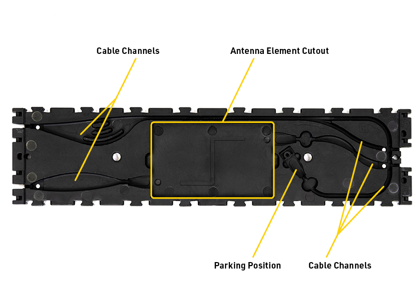
The design of the base element is assymetric, one end will additionally be marked as a splitting point and will have a different layout of the internal cable channels. When joining sequential antenna segments the splitting point ends should be joined directly together.
Sequential antenna segments are connected by joining the hinges to the 4 hinge slots on opposing ends of the black plastic base.
Antenna Element Cutout
The Ubidium Antenna Element fits securely in to the central cutout of the black plastic base, the antenna element must be positioned with the RACE RESULT logo facing vertically up. The horizontal orientation of the antenna element does not matter.
Cable Channels.
Each base element contains cable channels to secure and protect the Interconnecting Cables which run between the different antenna segments.
Each end of the base element contains 2 separate open channels, on the splitting end of the element they are in the center whereas on the non-splitting end they will be on the outer edges.
On each end, one cable channel connects to the Antenna Element of this segment, whereas the other will run around the outside edge of the Antenna Element to bypass this segment and connect to the next Antenna Element in that direction.
The channels which run to the Antenna Element of the current segment contain extra wide corners to allow for manufacturing tolerances in the length of the cable.
The antenna bypass channel contains an extra large cutout which then contains three different channels, this is to allow for extra slack to be stored securely inside the segment in the event of substantial difference in cable length.
The antenna bypass channel additionally splits in two distinct channels, one of these is used to connect the cable to the next antenna segment whereas the other is used for the parking position of the cable.
In the last segment of the antenna there will be excess cable, this should be stored in the parking position which runs around the outside perimeter of the base element and is denoted by a P symbol.
The parking position also has a cutout to safely store the coupling joint.