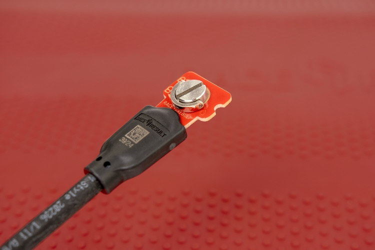
The Ubidium Ground Antenna is comprised of five key components.
- Black Plastic Base
- Red Plastic Cover
- Ubidium Antenna Element
- Ubidium Connector Cable
- Ubidium Interconnecting Cables
Each component has been carefully designed for maximum performance when used as part of the Ubidium Ground Antenna.
Black Plastic Base
The black plastic base sits on the ground and has cutouts to hold the Ubidium Antenna Elements and cables. It is then covered by the red plastic cover which slots in to place on the side and is secured using the Snap-In Buttons.
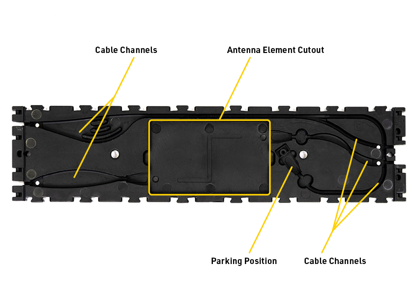
The design of the base element is assymetric, one end will additionally be marked as a splitting point and will have a different layout of the internal cable channels. When joining sequential antenna segments the splitting point ends should be joined directly together.
Sequential antenna segments are connected by joining the hinges to the 4 hinge slots on opposing ends of the black plastic base.
Antenna Element Cutout
The Ubidium Antenna Element fits securely in to the central cutout of the black plastic base, the antenna element must be positioned with the RACE RESULT logo facing vertically up. The horizontal orientation of the antenna element does not matter.
Cable Channels.
Each base element contains cable channels to secure and protect the Interconnecting Cables which run between the different antenna segments.
Each end of the base element contains 2 separate open channels, on the splitting end of the element they are in the center whereas on the non-splitting end they will be on the outer edges.
On each end, one cable channel connects to the Antenna Element of this segment, whereas the other will run around the outside edge of the Antenna Element to bypass this segment and connect to the next Antenna Element in that direction.
The channels which run to the Antenna Element of the current segment contain extra wide corners to allow for manufacturing tolerances in the length of the cable.
The antenna bypass channel contains an extra large cutout which then contains three different channels, this is to allow for extra slack to be stored securely inside the segment in the event of substantial difference in cable length.
The antenna bypass channel additionally splits in two distinct channels, one of these is used to connect the cable to the next antenna segment whereas the other is used for the parking position of the cable.
In the last segment of the antenna there will be excess cable, this should be stored in the parking position which runs around the outside perimeter of the base element and is denoted by a P symbol.
The parking position also has a cutout to safely store the coupling joint.
Red Plastic Cover
The red plastic cover fits over the base to protect the internal cables and antenna elements and provide a ramped edge to the mat. The underside of the cover includes the Snap-In Buttons which fit in to the black plastic base, and the guide joints additionally slot in to the base.
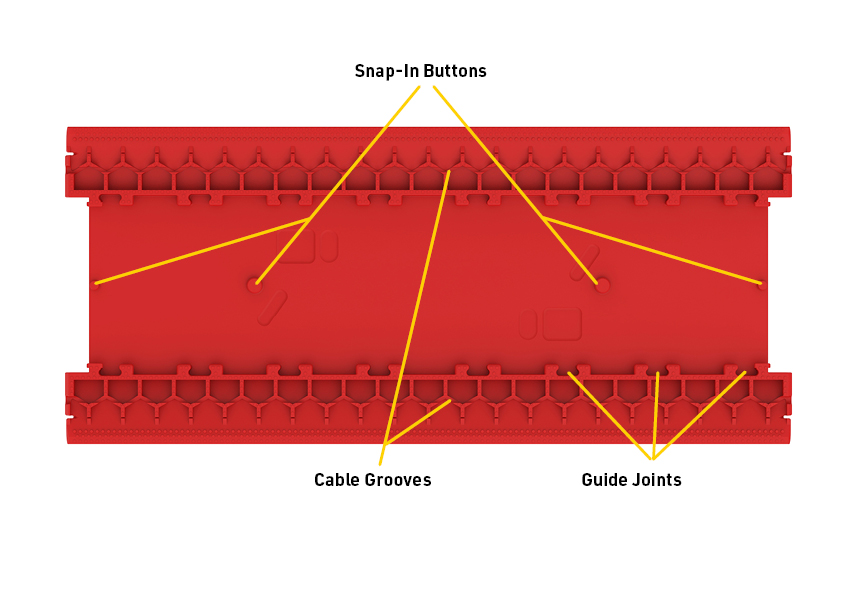
The cover is symmetrical and the orientation of installation does not matter.
The edges of the cover are designed to flex when setup to provide a smooth transition from the ground. Additionally on the underside of the edges is an additional groove which can be used to run additional cables such as power cables or Active Loop Cables.
Ubidium Antenna Element
Each antenna segment contains an Ubidium Antenna Element, which is a fully contained UHF Reader and Antenna module.
The antenna element should be installed in the cutout of the black plastic base with the RACE RESULT logo facing upwards. The antenna element can be connected to the Ubidium system through either connection
The element is connected to the system with the coupling joint, it does not matter to which.
The Ubidium Antenna Element will only work with the Ubidium System.
LED Indicator
Each Ubidium Antenna Element contains an LED which is used to indicate the status of the reader.
The LED will be turned on when the element is connected to an Ubidium system and powered on, the exception to this is when the system is updating the firmware of the element - the LED will be powered off.
A solid green LED indicates that the reader is operating normally with no transponders in range.
If the LED is flashing then this indicates that a transponder is being detected.
Coupling Joint
Ubidium Antenna Elements are connected to the system through the coupling joint, each antenna has 2 coupling joints, one on each end.
When connecting the antenna element to the system it does not matter to which end it is connected, but you must ensure to not create a loop where the element is connected to the system through both joints.
The coupling joint is cutout for the cable end plate and has a thread in the center, the cutout is then filled with a silicone seal which also protects the 4 contact pins. The locking screw of the cable end should then be screwed in to the thread, as the screw is tightened the silicone pad is compressed which allows the pins to make contact with the contact plates of the cable end. A tight seal also helps protect the connection against moisture and help prevent long-term corrosion.

Firmly tighten the screws with the supplied screw driver. The silicone is more resistant than the original foam and needs to be compressed to seal properly and press the connector against the brass nut.
Firmware
Each Ubidium Antenna Element stores the firmware on it's internal memory, the firmware of the element will be managed automatically by the Ubidium System. It is not possible to update individual elements separately from the system.
If combining elements which have been used with different systems it is therefore possible that different elements will be running different firmware. The system may therefore upgrade or downgrade elements when starting the system to try and ensure all elements can function together.
Ubidium Cables
The Ubidium cables are used to carry both power and data, you should not attempt to repair these cables as improper repairs may cause damage to both the system and antenna elements.
Connector Cable
The connector cable is used to connect the Ubidium Ground Antenna to the system.
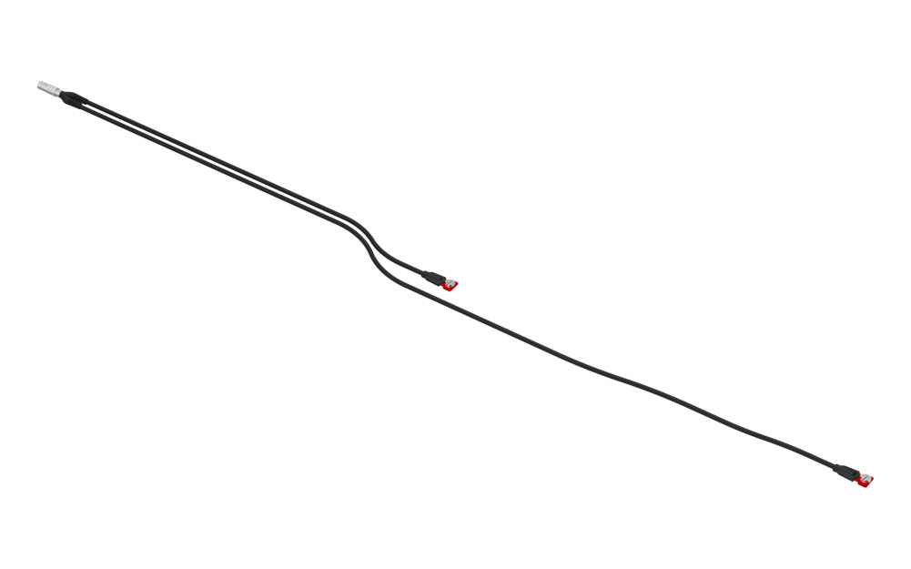
The main connector is plugged in to the Expansion Port of the Ubidium System and then splits in to two individual cables which are used to connect to the first and second Antenna Elements.
Reader Cables
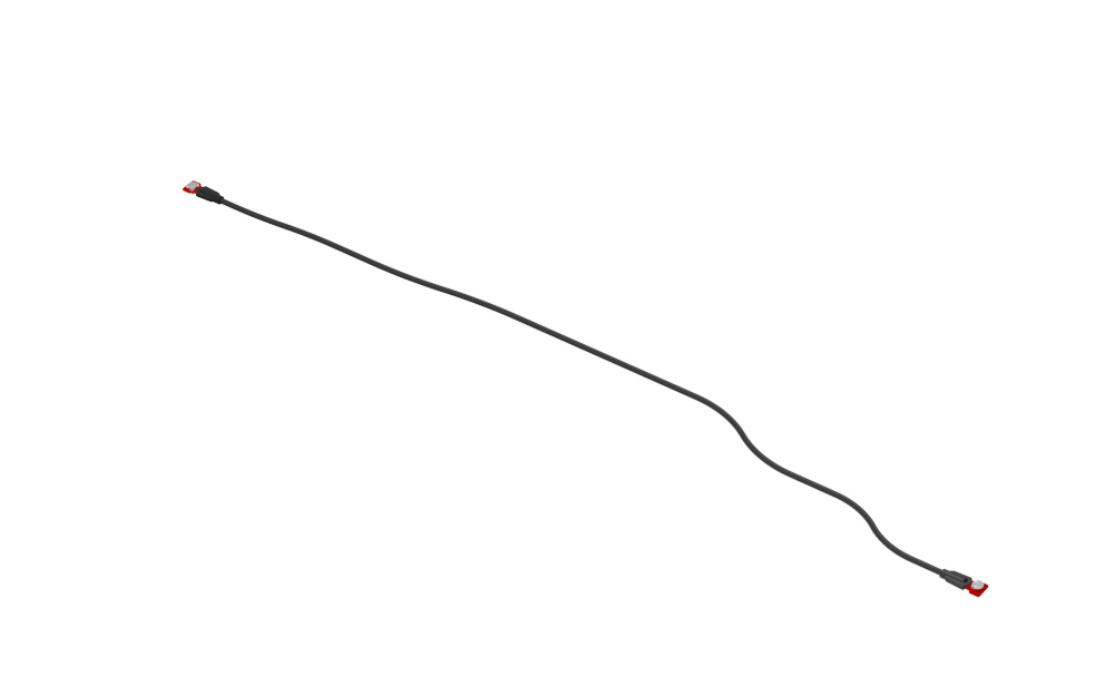
The reader cables are used to connect additional Antenna Elements to the Ground Antenna. The cable ends fit in to the coupling joint or should be stored in the parking position of the base when not in use.
Coupling Joint
The coupling joint is used to connect the cables to the Antenna Element. The central screw should be fully tightened using a flat-head screwdriver in the slot to ensure proper connection.