This document describes how to communicate with a USB Timing Box using the ASCII Protocol. This document is specifically designed for developers who wish to integrate the RACE RESULT USB Timing Box into their software.
This document describes Firmware version 2.4 and up.
Arrows in this document
← indicates data sent from the computer to the USB Timing Box.
→ indicates data replied from the USB Timing Box to the computer.
Quick Start in 3 steps
Open serial port using 19200 BAUD 8N1. Wait 3s before sending first command. Make sure DTR-Line is low.
Step 1) Switch to ASCII-Timing Protocol (only needed in FW 2.4)
← ASCII\n
→ ASCII;00\n
→ \n
Step 2) Pair & Sync computer time and internal time stamp
← EPOCHREFSET;4a3caa45\n
⇅ toggle DTR line
→ EPOCHREFSET;00\n
→ 4a3caa45;0151bcf5\n
→ \n
Step 3) Get passings
← PASSINGGET;00000000\n                       // get passings starting at 0
→ PASSINGGET;00\n                             // command echo, no error
→ 00000000;03\n                               // 3 passings available
→ GLBAS60;0718;01521527;0c;08;9f;1a;0;1;2;00;0\n
→ GLBAS70;04c1;01521536;14;09;9f;1a;0;1;2;00;0\n
→ EMPAL70;047c;0152153b;0e;08;9f;1a;0;1;2;00;0\n
→ \n
Serial Communication
Communication is established via a virtual serial port provided by a built-in USB-serial-converter (FTDI FT232R), with 19200BAUD 8N1. Make sure to have the latest FTDI drivers installed.
PULL Protocol
Your software always initiates any communication by calling a command. The USB Timing Box will immediately respond and then wait for the next call. There is one exception: prewarns. If you enable prewarns, data is pushed without notice (but only if no other command is processing/pending).
 The USB Timing Box only processes one command at a time. If you call a command, you must always wait for the response to finish, before sending the next command.
DTR-Line Reset
It is critical that you actively control the DTR-Line (Data-Terminal-Ready) and set it to LOW/false as default setting at all times. If the DTR line is HIGH/true for more than 500msec, the USB Timing Box will do a hard reset! This is intended behavior and allows a host application to reset the box to a known default state.
Hint: Some serial libraries will require you to specifically switch on DTR-Line handling when opening the connection.
RACE RESULT recommends using a terminal tool like HTerm to try and test the connection by manual commands. Make sure your tool of choice defaults DTR to low. PuTTY for example does not!
Known Issue "NON GENUINE DEVICE"
If you or your customer ever encounter a "NON GENUINE DEVICE" message sent from the USB Timing Box, please be assured that RACE RESULT does only source genuine devices. This problem is caused by an error in the FTDI driver. Please follow the steps here.
Boot Up Process
Bootloader
On power up, the USB Timing Box goes through a bootloader process. For 3 seconds after power up, the bootloader is waiting for instructions to upgrade the firmware. During these 3 seconds any character sent to the box will stop it from booting! This results in a "dead" box with LED continuously on.
 Do not send any data to the USB Timing Box within 3 seconds after power up or reset. It is best practice to wait 3s or until the USB Timing Box issues AUTOBOOT\n indicating, that the bootloader is done.
Debug Interface (FW 2.4)
USB Timing Box FW 2.5 and up automatically switches to ASCII-Timing Protocol. FW 2.4 and earlier boots up in a "debug interface". On FW 2.4 you are required to call ASCII\n to switch to the ASCII-Timing Protocol. Be aware that RACE RESULT does not recommend any use of the debug interface. The behavior of the debug interface can change without notice. On FW 2.5 and up, you can switch back to debug interface by issuing the DEBUG\n command.
Reset
There are two ways to reset the USB Timing Box:
- Pull the DTR-Line HIGH/true for more than >500ms
This does not work in a waiting bootloader state. - Issue a RESET\n command.
It is recommended to use this command for testing purposes only.
The box will never perform a reset on its own.
Test boot up by intentionally resetting the box
← RESET\n
→ rrActive\n        //immediately at power up, LED ON
→ AUTOBOOT\n        //after 3 seconds, LED OFF
← ASCII\n           //not necessary for FW 2.5 and newer
→ ASCII;00\n
→ \n
Time Base
Ticks
The USB Timing Box operates on a 0.28ppm time base, counting 256 ticks per second.
Time Stamps
The USB Timing Box does not know the true date and time. It does not know about leap days or seconds. It has no built-in calendar. All times are internally stored as 32 bit time stamps with 256th of a second resolution. As stored passings can be up to 24 hours old. On startup, the USB Timing Box time stamp starts running from 24 hours worth of ticks to avoid negative passing time stamp values.
Computer Time Reference - EPOCHREF
In order to translate a passing time stamp to a real world computer time, you need to reference the internal time base to your computer time. At the point in time you call EPOCHREFSET and pull the DTR-Line HIGH, you create a synchronized value pair:
ref_time_stamp @ ref_computer_time
Where ref_time_stamp is the internal USB Timing Box time base value at synchronization and ref_computer_time is a value set by your application. Both values are stored as a pair in the USB Timing Box. You can always read this value pair with EPOCHREFGET. If your software or computer crashes, the USB Timing Box will keep the correct event time for you. To convert a pass_time_stamp to a real world computer time, you must calculate:
Computer_Time(pass_time_stamp) =
ref_computer_time + ((pass_time_stamp - ref_time_stamp) / 256.0)
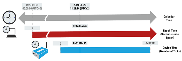
RACE RESULT strongly recommends using the standard UNIX TIME for your computer time reference value. https://en.wikipedia.org/wiki/Unix_time
| Unix Time Epoch | USB Timing Box Time Stamp (FW 2.5 and below) | USB Timing Box Time Stamp (FW 2.6 and up after <CONFSET;B3;1>) | |
| Data | 32bit | 32bit | 40bit |
| Start | 1. Jan 1970 | Last USB Timing Box start up / reset | Last USB Timing Box start up / reset + 7 days |
| Resolution | 1 second | 256th of a second | 2048th of a second |
| Overflow | 19. Jan 2038 | after 193 days of operation | 2^40 / (2048*3600*24*365) = 17 years |
| Init value | 0 | 24*3600*256 = 22.118.400 (24h) | 7*24*3600*2048 = 1.238.630.400 (7 days) |
Commands
Calling a Command
Commands always start with the uppercase name, which can be followed by parameters which are separated by a semicolon and terminated with a newline \n.
Reply
Replies always start with an echo of the command followed by a semicolon and a return code indicating success or error. The next lines contain the response of the call. Every response line is terminated with a single \n newline character. The reply is finally terminated with another \n newline character. It is best practice to wait for a double \n\n new line as indication for the end of the call. \n\n will never be part of the response data.
Parameters and Response Values
All numbers are transferred as hex numbers, without any prefixes (like 0x), in lowercase letters and always with leading zeros.
Return Codes
|
00 |
success, no error |
|
10-1f |
command specific error, see command description |
|
ff |
error unknown command or parameter(s), unless caught by return codes 10-1f |
Command ASCII
The ASCII command must be sent to the device (FW 2.4 and earlier), to switch to ASCII-Timing Protocol communication mode and make all other commands in this document available.
ASCII resets all communication parameters to default values. This is to ensure that your application can always call ASCII as a first command talking to a new box and be sure the communication itself is on default values.
ASCII resets:
- Push Prewarn OFF
- Push Passings OFF
- Check Sum Mode OFF
For backwards compatibility ASCII can be used without Check Sum, even when Check Sum mode is enabled.
Call
ASCII\n
Reply
ASCII;00\n
\n
Command SITESURVEY (FW 2.5 and up only)
Scans all eight 2.4Ghz channels and reports noise values. These can be used to select a suitable channel.
 The 2.4GHz receiver will be blocked for about 2 seconds. In this period it is not possible to receive any transponder data. Do not call this command during normal timing operation!
Call
SITESURVEY\n
Reply
SITESURVEY;00\n
00;[Noise:2]\n
01;[Noise:2]\n
02;[Noise:2]\n
03;[Noise:2]\n
04;[Noise:2]\n
05;[Noise:2]\n
06;[Noise:2]\n
07;[Noise:2]\n
\n
Response
[Noise] | 00 = no noise |
A channel with more than >50% noise is not recommended to be used.
Example:
← SITESURVEY\n
→ SITESURVEY;00\n
→ 00;02\n
→ 01;00\n
→ 02;02\n
→ 03;03\n
→ 04;07\n
→ 05;09\n
→ 06;0a\n
→ 07;04\n
→ \n
You should select the second channel (note that there is a -1 offset in internal channel numbering)
Note: You can always read the noise level of the current channel by calling BEACONGET
Command CONFSET
Sets the parameter [parameter-id] to the value [value].
Call
CONFSET;[parameter-id:2];[value:2]\n
Reply
CONFSET;[error-code]\n
[parameter-id:2];[value:2]\n
\n
Example (set loop power to 50%)
← CONFSET;08;32\n
→ CONFSET;00\n
→ 08;32\n
→ \n
Error codes
00 success, no error
10 parameter-id out of range
11 value out of range
Command CONFGET
Call
CONFGET;[parameter-id:2]\n
Reply
CONFGET;00\n
[parameter-id:2];[value:2]\n
\n
Example (get loop power)
← CONFGET;08\n
→ CONFGET;00\n
→ 08;32\n
→ \n
Error codes
10 parameter-id out of range
Configuration parameter IDs and values/range
Parameter [parameter-id] |
Description |
Possible Values |
| 01 |
Push Pre-warn (non persistent) |
00=disabled (D) |
| 02 |
Blink/beep on repeated passing (non persistent) |
00=disabled |
| 03 |
Impulse input or beep output |
00=impulse-in |
| 04 |
Auto-shutdown on power loss (non persistent) |
00=disabled (D) |
| 05 |
Operation Mode |
05=usb-kiosk |
| 06 |
Channel ID |
00 - 07 |
| 07 |
Loop ID |
00 - 07 |
| 08 |
Loop Power |
00 - 64 |
| 09 |
Blink dead-time |
02 - FF |
| 0a |
Charging via USB |
00:disabled |
| 0b |
Use DTR |
00:disabled |
| 0c |
Alternate Channel Switching (FW 2.5 and up) |
00:disabled |
| a0 |
Tray Scan Power |
01 - 64 |
| a1 | Tray Scan interval Time span for which a single row or column is powered. |
01 - FF in ticks (1/256th) (default 50) |
| a2 |
Tray Scan ramp up delay |
01 - FF in ticks (1/256th) |
| a3 |
Tray Scan row to column delay |
01 - FF in ticks (1/256th) (default E0) |
| a4 |
Repeat Row and Column cycle for another N repetitions |
01 - 0A |
| b1 |
Enable CheckSum for all ASCII Protocoll communication (see here) |
0 - 1 (default 0) |
| b2 |
Push Passings enable. Only applys to FW 2.6 and up. Values of 1 and 255 lead to endless pushing of passings Values > 1 and <= 254 tell the box to push exactly this number of passings. You need to refresh this value again if you want to receive the next passings. |
0 - 1 / 2..254 (default 0) |
| b3 | Enable FW Version 2.6 data reporting format (Signed Temperature, New Beacons Info, Timestamps with 2048th and dayadj) | 0 - 1 (default 0) |
| b4 |
Enable Status Push Message every second: #S;[TickCount:8];[MainLoopCycles:4];[LoopStatus:2];[MeasuredLoopPower:2];[ChannelNoise:2];[BattPercent:2]\n\n #S;015405f2;11f7;00;2c;01;3b\n\n |
0 - 1 (default 0) |
Parameters 06-08 are stored in a non-volatile memory on power down.
Command INFOGET
Query general information. This command replies 2 or 4 hex-digits of data, depending on the queried value.
Call
INFOGET;[parameter-id:2]\n
Reply
INFOGET;00\n
[parameter-id:2];[value:{2,4}]\n
\n
| Parameter [parameter-id] |
Description | Value Mapping [value] |
| 01 | Decoder ID 4 digits |
(0000 - ffff) => (0 - 65535) 1387 = 4999 = A-4999 |
| 02 | Firmware Version 2 digits |
(00 - ff) => (0 - 255)/10 18 = 24 = v2.4 |
| 03 | Hardware Version 2 digits |
(00 - ff) => (0 - 255)/10 18 = 24 = v2.4 |
| 04 | Box Type 2 digits |
0a = active-ext 1e = management-box 28 = usb-timing-box |
| 05 | Battery Voltage 2 digits |
(00 - ff) => (0 - 255)/10 [V] 28 = 40 = 4.0V |
| 06 | Reserved | |
| 07 | Battery State 2 digits |
0 = Fault 1 = Charging 2 = Reduced Charging 3 = Discharging |
| 08 | Battery Level 2 digits |
(00 - ff) => (0-100)% 4e = 78 = 78% |
| 09 | Internal Temperature 2 digits |
(00 - ff) FW 2.6: (-ff ... +ff) |
| 0a | Supply Voltage 2 digits |
(00 - ff) => (0 - 255)/10 [V] 31 = 49 = 4.9V |
| 0b | Loop Status 2 digits |
0 = loop ok f = internal error (PIC not running) |
| 0c | Built Revision (FW 2.5 and up) String |
-internal use- |
| 0d |
Measured Loop Power (FW 2.6 and up) 2 digits |
(00 - 64) Real Loop power in %. Hint: Loop power regulation may take several seconds after a new loop power setting to apply. Loop power regulation has a hysteresis to avoid oscillation, it is normal to not hit the exact value. Expect variances of up to +-2% to the set value. |
| 0e | Noise Status (FW 2.6 and up) 2 digits |
(00 - 0A) Noise on current channel in same scale as sitesurvey |
Command EPOCHREFGET
Returns the value pair which was stored in the USB Timing Box at the last call of EPOCHREFSET.
When connecting to a USB Timing Box, it is recommended to first send the command EPOCHREFGET to ensure there is no computer time reference value pair already set.
Call
EPOCHREFGET\n
Reply
EPOCHREFGET;00\n
[ComputerTime:8];[TimeStamp:8]\n
\n
Response
[ComputerTime] | computer reference time stored in the USB Timing Box with the last call of EPOCHREFSET. On startup, the computer time reference is cleared, hence the reply will be 0 if it is not set. |
[TimeStamp] | the time stamp stored in the USB Timing Box at the last call of EPOCHREFSET. On startup, the time stamp reference is cleared, hence the reply will be 0 if it is not set. |
Example
← EPOCHREFGET\n
→ EPOCHREFGET;00\n
→ 4a3caa45;0151bcf5\n            // ref_computer_time;ref_time_stamp
→ \n
Command EPOCHREFSET
Syncs and stores the computer time reference in the USB Timing Box. This command should be executed upon connecting, if the computer time reference is not set yet.
Call
EPOCHREFSET;<epoch:8>\n
Reply
EPOCHREFSET;00\n
[ComputerTime:8];[TimeStamp:8]\n
\n
Reply after 2s DTR timeout
EPOCHREFSET;10\n
\n
Response
|
[ComputerTime] |
new computer reference time stored in the USB Timing Box. |
|
[TimeStamp] |
Internal time base time stamp captured and stored in the USB Timing Box at DTR-Line trigger. |
Example
← EPOCHREFSET;4a3caa45\n     // June 20 2009 11:22:14 UTC+2 == 0x4a3caa45
⇅ toggle DTR line           // Time set on rising edge of DTR
→ EPOCHREFSET;00\n
→ 4a3caa45;0151bcf5\n        // ref_computer_time;ref_time_stamp
→ \n
0x4a3caa45 is the current number of computer time seconds since 1. Jan 1970. The time is set when the DTR line is toggled. The response returns the computer time and the corresponding internal time stamp at that moment.
Within 2s of your EPOCHREFSET call you need to briefly set the DTR-Line to HIGH to trigger the actual time synchronization. Best practice is to call EPOCHREFSET with the next full seconds EPOCH and then poll your computer system time in a loop until the full second time is reached to then "trigger" the sync by setting the DTR-Line HIGH for 200ms.
This pseudocode describes the needed operation on your computer:
cmdString = "EPOCHREFSET;" + toHex(epoch_Time_Now() + 1) + "\n"     // cmdString == 'EPOCHREFSET;4a3caa46\n'
write_Serial ( cmdString )
wait_until_next_second()
set_Serial_DTR ( HIGH )                              // Time set on rising edge of DTR
sleep_200ms ()
set_Serial_DTR ( LOW )
sleep_200ms ()
rcv = read_next_line_Serial()                        // rcv == 'EPOCHREFSET;00\n'
rcv = read_next_line_Serial()                        // rcv == '4a3caa46;0151bcf5\n'
ref_computer_time = split_into_array( rcv, ";")[0]   // ref_computer_time == 0x4a3caa46
ref_time_stamp = split_into_array( rcv, ";")[1]      // ref_time_stamp == 0x0151bcf5
You should store ref_computer_time and ref_time_stamp in your application for processing passings.
This DTR-Line procedure is needed to ensure the best possible accuracy in the presence of operating system data buffering on the SERIAL port. In case your serial implementation has no control over the DTR line, you can disable the DTR line of the USB Timing Box calling
CONFSET;0b;00\n
Command TIMESTAMPGET
Gets the current time stamp of the USB Timing Box.
Note: Do not use for timing calculation purposes! Your operating system serial port data buffer is introducing unpredictable delays.
Call
TIMESTAMPGET\n
Reply
TIMESTAMPGET;00\n
[TimeStamp:8]\n
\n
Example
← TIMESTAMPGET\n
→ TIMESTAMPGET;00\n
→ 0151bcf5\n
→ \n
Command PASSINGINFOGET (FW 2.5 and up)
Reports information about passings in the internal buffer.
Call
PASSINGINFOGET\n
Reply
PASSINGINFOGET;00\n
[Count:4];[StartID:8];[StartTimeStamp:8]; [LastID:8];[LastTimeStamp:8]\n
\n
Response
[Count] | Number of passings in buffer. |
[StartID] | Index of first passing in buffer. |
[StartTimeStamp] | Time stamp of first passing in buffer. |
[LastID] | Index of last passing in buffer. |
[LastTimeStamp] | Time stamp of last passing in buffer. |
Example
← PASSINGINFOGET\n
→ PASSINGINFOGET;00\n
→ 0002;00000000;002b6efc;00000001;00823aa8\n        // 2 passings
→ \n
Hint:
When the buffer is empty, the reply will look like this with all indices = 0 (which obviously point to no passing):
← PASSINGINFOGET\n
→ PASSINGINFOGET;00\n
→ 0000;00000000;00000000;00000000;00000000\n
→ \n
Command PASSINGGET
The USB Timing Box has an internal buffer, storing up to 1000 passings. Every passing is assigned with a 32bit index number, starting with 0 from startup. The index of the first passing you would like to receive in this request must be supplied as parameter.
PASSINGGET can reply with up to 64 passings at a time, therefore after one response of 64 passings, you should immediately check again, with the new minimum index being 64 higher than the last request.
Parameters
|
[StartIndex] |
Passing index of the first passing in request |
|
[Count] |
The number of passings which will be returned in this request |
|
<passing(i)> |
The returned passing with passing index i |
|
[MinStartIndex] |
The lowest [StartIndex] available. |
Error codes
10 [StartIndex] too low - telling you that there longer exists a <passing(i)>
Call
PASSINGGET;[StartIndex:8]\n
Reply (Error Code 00 = no error)
The function replies the [StartIndex] value it was called with. This is so you can check that there was no communication problem leading to a wrong index.
The second reply is [Count] indicating how many passing records will follow.
PASSINGGET;00\n
[StartIndex:8];[Count:2]\n
<passing([StartIndex])>\n
<passing([StartIndex]+1)>\n
...
<passing([StartIndex]+[Count]-1)>\n
<passing([StartIndex]+[Count])>\n
\n
Reply with Error Code 10
The function replies the [StartIndex] value it was called with. This is so you can check that there was no communication problem leading to a wrong index.
The second reply is [MinStartIndex] indicating the lowest [StartIndex] that is available in memory.
PASSINGGET;10\n
[StartIndex:8];[MinStartIndex:8]\n
\n
In case of error 10, you need to execute PASSINGGET;[MinStartIndex] again.
Example
← PASSINGGET;0\n
→ PASSINGGET;00\n
→ 00000000;02\n
→ ZBAAA03;04c6;002b6efc;11;19;1d;15;0;1;1;00;0\n
→ ZBAAA03;04c7;00823aa8;1e;1a;1d;15;0;1;1;00;0\n
→ \n
Command BEACONGET
Beacons are status data packets sent by all active boxes once per second. This way, you can check signal quality, power status and settings of all boxes available in your timing setup. It is recommended to monitor this data and alert if an Active System can no longer be seen, power is low, or otherwise.
Call
BEACONGET\n
Reply
BEACONGET;00\n
[BeaconCount:2]\n
<beacon(0)>\n
...
<beacon([BeaconCount]-1)>\n
<beacon([BeaconCount])>\n
\n
Response
|
[BeaconCount] |
The number of passings which will be returned in this request |
|
<beacon(i)> |
The returned beacon i, as described in the next section |
Example (single beacon, standard format)
← BEACONGET\n
→ BEACONGET;00\n
→ 01\n
→ 3039;1;10;17;64;7;1;1;31;245d;00000000;03;00;00;21;00;00\n
→ \n
Example (3x beacons, additional FW2.6 data fields after <CONFSET;B3;1>)
← BEACONGET\n
→ BEACONGET;00\n
→ 03\n
→ 06f6;0;03;25;32;5;2;0;7b;11fd;095fe75000;03;02;00;00;99;24;00;1a;14;21;+20;0;00;00;00\n
→ 9dd0;1;00;05;1e;5;0;0;a9;00b5;095fe72300;03;0a;00;00;bf;2d;00;1a;50;81;+26;0;00;00;00\n
→ 3039;1;10;15;64;5;1;1;31;255e;095fe72302;03;06;00;20;00;00;00;1a;1e;35;+1d;0;04;00;00\n
→ \n
Beacon Format
[ActiveDeviceID:4];[LoopStatus:1];[Mode:2];[LoopData:2];[LoopPower:2];[Channel:1];[LoopId:1];[PowerConn:1];[PowerStatus:2];[BeaconIndex:4];[Time:8];[N/A:2];[ChNoiseAvg:2];[TransLQI:2];[TransEnergyDetect:2];
[BeaconLQI:2];[BeaconEnergyDetect:2]
FW2.6 format after setting <CONFSET;B3;1>
[ActiveDeviceID:4];[LoopStatus:1];[Mode:2];[LoopData:2];[LoopPower:2];[Channel:1];[LoopId:1];[PowerConn:1];[PowerStatus:2];[BeaconIndex:4];[Time:10];[BeaconVersion:2];[ChNoiseAvg:2];[RFU:2];[TransponderEnergyDetect:2];
[BeaconLQI:2];[BeaconEnergyDetect:2];[beaconSuccessRate:1];[FWVersion:2];[boxType:2];[boxMode:2];[temperature:+2];[bufferOverflow:1];[bufferFillState:2];[avgTransponderRetries:2];[avgRepeatRetries:2]
|
[ActiveDeviceID] |
Device ID of system |
|
[LoopStatus] |
0 = loop ok |
|
[BeaconMode] |
0x00 = Active Extension or USB Timing Box in Timing Mode 0x10 = No Timing Device (Management Box, USB Timing Box in Kiosk mode etc...) 0x21 = Tracking Start 0x22 = Tracking Stop |
|
[LoopData] |
Reserved |
|
[LoopPower] |
Current power setting of the device (00 - ff) => (0 - 256) |
|
[Channel] |
Channel ID (0 - f) => (1 - 8) |
|
[LoopID] |
Loop ID, (0 - f) => (1 - 8) |
|
[PowerConn] |
0 = 12V |
|
[PowerStatus] |
If [PowerConn] == 2, [PowerStatus]== battery remaining in hours |
|
[BeaconIndex] |
Index of beacon sent, count from number of beacons sent since startup |
|
[Time] |
The current number of ticks for the system Standard Format: 32 Bit - 256th seconds FW 2.6 Format: 40 Bit - 2048th seconds |
|
[N/A] |
Not in use |
|
[ChNoiseAvg] |
Average noise level of current channel [0..10] with 0 = no noise |
|
[TransLQI] |
Average Link Quality Indicator for communication between the Active System and all transponder seen since startup |
|
[TransEnergyDetect] |
Average RSSI for communication between the Active System and all transponders seen since startup Values are from 0..85. You need to calculate -90+TransEnergyDetect to get RSSI values from -90dBm...-5dBm |
|
[BeaconLQI] |
Average Link Quality Indicator for communication between the Active System and the base system (Loop ID == 1) seen since startup |
|
[BeaconEnergyDetect] |
Average RSSI for communication between the Active System and the base system (Loop ID == 1) seen since startup |
| [beaconSuccessRate] | 0..10 - with 10 = all expected beacons received and 0, no beacons received at all |
| [FWVersion] | 26 = 2.6 |
| [boxType] | 0A=Active Extension, 0x14=Loop Box, 0x1E=Management Box, 0x28=USB Timing Box, 0x50=Ubidium |
| [boxMode] | See Box Mode Table |
| [temperature] | Temperature of Mikrocontroller in C° |
| [bufferOverflow] | 1=at least one buffer overflow since last boot, 0=no buffer overflow so far |
| [bufferFillState] | 0..100% with 100% = buffer full |
| [avgTransponderRetries] | ACKS + BUSY, 0 is good, 1..2 is OK, everything above means there is a problem |
| [avgRepeatSuccessRate] | 0...100% - with 0% very good, 100% very bad. >50% is not good. |
Step-By-Step Guide
Open the port using 19200 baud, 8N1. Wait for 3s before sending any command after start up.
Switch to ASCII-Timing protocol
← ASCII\n
→ ASCII;00\n
→ \n
Check/Create Time Reference
When you connect to the device, there may already be a time reference set for the device. Check if the time is already referenced (e.g. because your PC crashed during the event) before changing the time reference. Do this by sending the EPOCHREFGET command to the system.
Ask the USB Timing Box for stored value pair
← EPOCHREFGET\n
→ EPOCHREFGET;00\n
→ 00000000;00000000\n		// ref_computer_time;ref_time_stamp
→ \n
Store the result for later use with your application.
If values are not set yet, set time reference to current time.
← EPOCHREFSET;4a3caa45\n
⇅ toggle DTR line
→ EPOCHREFSET;00\n
→ 4a3caa45;0151bcf5\n		// ref_computer_time;ref_time_stamp
→ \n
Store the result for later use with your application.
System Setup and Monitoring
← INFOGET;01
→ INFOGET;00\n
→ 01;1387\n
→ \n
Read the Device ID, 0x1387 = 4999, to distinguish own from foreign beacons later.
← CONFSET;05;06\n
→ CONFSET;00\n
→ 05;06\n
→ \n
Ensure the device is in USB Timing Mode.
← CONFGET;07\n
→ CONFGET;00\n
→ 07;00\n
→ \n
It is recommended to check the Loop ID and display a warning in your application if it is not 0x00 == 1. Passings created by Loop Boxes are only received by Loop ID 1.
Check beacons in regular intervals
← BEACONGET\n
→ BEACONGET;00\n
→ 02\n
→ 0685;0;03;22;00;2;2;0;31;00b2;01539ffb;1b;02;00;00;ff;4f\n
→ 1387;1;00;02;0a;2;0;0;31;0221;00000000;1b;02;00;00;00;00\n
→ \n
It is recommended to check for loop errors and critical battery levels and inform the user. All critical information for the Box itself is contained in the Beacons, therefore in most situations there is no need to additionally check it with INFOGET.
Passings
You must keep track of the number of received passings to calculate the correct [StartId] for the next PASSINGGET call.
Example 1 - Empty passing buffer at start
← PASSINGGET;00000000\n       <1>
→ PASSINGGET;00\n             <2>
→ 00000000;00\n               <3>
→ \n[...some time later, after creating passings...]
← PASSINGGET;00000000\n       <4>
→ PASSINGGET;00\n             <5>
→ 00000000;03\n               <6>
→ GLBAS60;0718;01521527;0c;08;9f;1a;0;1;2;00;0\n
→ GLBAS70;04c1;01521536;14;09;9f;1a;0;1;2;00;0\n
→ EMPAL70;047c;0152153b;0e;08;9f;1a;0;1;2;00;0\n
→ \n
[... small wait between requests ...]
← PASSINGGET;00000003\n       <7>
- Try to recieve passings starting at 0x00000000,…
- …no error code
- …no passings available ? [StartID] still 0x00000000
- Try to receive passings again
- …still no error
- …we have 0x03 passings, starting with ID 0x00, following in the next lines.
- Next try, receive passings from [StartID]==0x00000003 onwards
Example 2 - More than 64 passings
← PASSINGGET;00000000\n
→ PASSINGGET;00\n
→ 00000000;40\n               <1>
→ GLBAS60;0718;01521527;0c;08;9f;1a;0;1;2;00;0\n
→ GLBAS70;04c1;01521536;14;09;9f;1a;0;1;2;00;0\n
[...]
→ SNRMT06;1260;015215d8;0d;0c;9f;15;0;1;2;01;0\n
→ SNRMT07;2910;015215c9;30;0f;9f;15;0;1;2;01;0\n
→ \n
- Number of passings sent in this response is 0x40 == 64. We should call the command again as there may be more passings which have not been sent.
← PASSINGGET;00000040\n       <2>
→ PASSINGGET;00\n
→ 00000040;05\n               <3>
→ GLBAS98;04d3;015215c9;11;08;9f;1a;0;1;2;01;0\n
→ GLBAS58;074b;0152154d;11;0a;9f;1a;0;1;2;03;0\n
→ SNRMT29;2ad4;01521590;47;0f;9f;15;0;1;2;02;0\n
→ GLBAS78;04e0;01521594;0f;09;9f;1a;0;1;2;02;0\n
→ SNRMT39;111e;01521594;2e;0e;9f;15;0;1;2;04;0\n
→ \n
- Read further passings, starting with 0x40
This transmission only contains 0x05 passings => buffer fully read
Example 3 - Buffer overflow or StartID too high
← PASSINGGET;00000000\n
→ PASSINGGET;10\n             <1>
→ 00000000;0000021d\n         <2>
→ \n
- Error 10 StartID out of range. Passing 0x00 (original [StartID] in query) has been deleted as the buffer has overflowed.
- The first available passing has the ID 0x21d = 541, so there are passings
0x21d = 541 to 0x21d + 0d1000 = 0x604 = 1540 available.