Minimum distance between two loops
Sometimes you may want to set up 2 loops close to each other to measure speed at a certain point on the course, but it is important to know that a transponder has an internal dead time when it cannot be activated.
As such we suggest as a general guideline that the minimum distance between 2 loops is the MAX speed in km/h divided by 10. For example if you expect a max speed of 160 km/h (100mph) then a minimum distance of 16m between the 2 loops should be used.
Active System 2.4GHz Frequencies
The RACE RESULT active system communicates via the 2.4GHz frequency, there are 8 channels to choose from each with a unique frequency. Each channel also has a backup frequency, meaning it will switch between the Main and Backup Frequencies which aids transmission in environments where there is high noise.
The backup frequency is used by V2/V3 Transponders and up.
Old Decoder Firmware and FW 2.5 Active Boxes: When the channel switching of a decoder is set to AUTO it will automatically disable this when a V1 transponder is detected, this will only reset when the system is restarted. This is the recommended setting. Loop Boxes all use AUTO mode by default and this cannot be changed.
Ubidium and FW 2.6 Active Boxes: Permanently switch frequencies. Therefore use of V1 Transponders is not recommended.
| Channel | 1 | 2 | 3 | 4 | 5 | 6 | 7 | 8 |
|
Main Frequency [MHz]: |
2480 |
2405 |
2425 |
2475 |
2415 |
2460 |
2435 |
2450 |
| Backup Frequency [MHz] |
2410 |
2470 |
2465 |
2440 |
2445 |
2430 |
2455 |
2420 |
2.4GHz Test Mode (V2 Boxes FW 2.5 and up only)
The 2.4GHz Test Mode on the USB Timing Box, the Loop Box, and the Management Box allows advanced users to check channels for interference and make sure the 2.4GHz frontend and antenna are working correctly.
To get into Test Mode and check for noise:
- Ensure the device is switched off and has the 2.4GHz antenna connected.
- Press and hold the button, and continue to hold the button until the following screen is shown.
B RSSI=00 LQI=00 CH# 8 NOISE=02 - Press the button to cycle through the channels.
- Ensure that no transponders are activated and no other boxes nearby are operating on the same channel.
- Stay on each channel for at least 3 seconds. Look for the channel showing the lowest value for noise. Noise should show a value below 10.
- To return to normal operation, press and hold the button until the red LED turns on then release the button to resume normal startup.
- For timing purposes, set the box to the channel showing the lowest noise value.
Testing Box 2.4GHz performance (and antenna)
- Boot two boxes into test mode as above and set them to the same channel.
- Place them approximately 1m apart on a table.
- Ensure that no other boxes are on the same channel within connection range and no transponders are activated by the boxes.
- Point both the antennas upwards so that they are parallel to each other:
| B RSSI=65 LQI=55 |
| CH# 8 NOISE=33 |
With two V2 boxes, you should see a RSSI Value of at least 60, higher is better. If you see a RSSI value of 60 or better, you know that both boxes and both antennas are working OK.
Noise values can be ignored in this setup.
Testing a Transponder 2.4GHz performance:
Disconnect the loop and hold a transponder against the loop connector terminals to activate it. You should see similar values on the screen.
| T RSSI=75 LQI=55 |
| CH# 8 NOISE=33 |
You should see a RSSI Value of at least 75, higher is better. If you see a RSSI value of 75 or better, you know that the transponder and the box (and its antenna) is working OK.
Noise values can be ignored in this setup.
Testing 2.4GHz performance of an Active Extension:
The active extension does not support this test mode. But you can still test it (and its antenna) with a second box. Set the channel on the decoder to the channel you want to test on and follow the steps for testing a box.
Parameters:
Below is a description of each of the indicators on the screen:
|
Location on screen |
Description |
|
|
B/T |
Top left |
Indicates from what source the values on the screen are calculated from. B = Beacon = Other Box, T = Transponder |
|
RSSI |
Top center |
Received Signal Strength Indicator - measure of received signal power |
|
LQI |
Top right |
Link Quality Indicator (used for internal testing only) |
|
CH# |
Bottom left |
Channel ID |
|
NOISE |
Bottom right |
Noise level of channel |
Active High Noise Warning
A High Noise warning when using an Active Extension is triggered when there is large interference on the 2.4GHz channel which is being used, this can come from common things such as TV cameras, drones, wireless microphones, bluetooth or even public Wi-Fi hotspots. It may also be that the noise warning has been triggered by a Loop Box and so it is important to check your whole surrounding area.
Our 2.4GHz channels can be used alongside other devices on the same frequency, but if these are too strong or transmitting large bursts of data then it can interfere with the detections, with V2 Transponders the interference has been reduced by introducing a secondary backup frequency on all channels.
If possible you should remove the source of the 2.4GHz interference or move it away from your systems, if this is not possible then the channel scanner will show you the best channel to use in your current setup. If you do change channels on your Active Extension then don't forget to also change your Loop boxes and you may also need to change your automatic timing point selection in race result 11.
What Causes Loop Limit
Loop Limit means that the Active System was not able to apply the selected Loop Power to the attached Loop.
Think of a car: You push the pedal to the metal, but you are going up a hill and it can't go faster. The car knows that you would want it to go faster, but it can't.
Loop Limit is mainly caused by inductance of the loop which is determined by:
- to long loop cable
- to thin loop cable
- loop cable coiled up or wound around metal
- to much metal around the loop
With our standard length cable you should rarely see a loop limit. With everything longer you will get a loop limit if you request 100%. This is due to regulatory limits. On longer loops it is simply not allowed to have 100% loop power.
Detections with Invalid Loop ID / Channel ID
It can happen that an Active Transponder will generate a passing with an invalid Channel ID / Loop ID, these are most commonly received as stored passings due to the cause for triggering them. Normally these invalid passings have just a single hit and there are 3 possible causes that we have identified:
Corrupt Data From Loop
When on the edges of the loop field the data packet received by the transponder can be corrupted, this results in the Transponder storing a passing with the incorrect Channel / Loop ID and a single hit. This was fixed in V2 transponders from November 2017, the new configuration requires 2 hits for a valid passing.
Participants Standing on Loops (Swim Starts)
The most common time this happens is during rolling swim starts when participants are stood directly on or near the loop for long periods of time. This results in similar corrupt data packets as above which would normally be ignored but due to the rapid consecutive detections the transponder may incorrectly store an invalid passing. This can happen to any ActiveTransponder
External Interference
The 125kHz channel is not unique to RACE RESULT transponders, and transponders may sometimes be activated by external electrical interference such as power cables and store a passing, which could be from the day before. This rarely happens to new V2 transponders due to the new configuration but can happen to any transponder if the interference is strong enough to cause multiple hits.
Solutions
If you have older ActivePro V1 Transponders we offer a trade-in program to upgrade to V2 transponders which eliminate most of the invalid passings.
Your decoder has an option to discard all stored passings, if you are not working with stored passings then you could choose to discard stored passings, as these issues are always reported as stored passings then they will be discarded. Warning: You may lose valid detections which have been stored by the transponder which could not be transmitted directly to the Active Extension or Loop Box.
In firmware version 2.26 we introduced an option to discard all passings below X number of hits. We have found that nearly all invalid passings are reported with a single hit, so setting this to discard all passings below 2 hits can solve this, you can also set the value higher if you are seeing lots of invalid passings with more than 1 hit. WARNING: This will discard ALL passings with less than X hits, so if you do have valid detections with a single hit they will be lost, but if you have passings with low hits then you should check your setup as a single hit suggests there is a problem with the loop setup.
Effect of KeylessGo on Active Transponders
There is a high likelihood that KeylessGo cars cause unintended stored passings on Active Transponders. Especially when unlocking a door or starting the engine of a KeylessGo car this tends to occur. These unwanted detections can result both in a shorter battery life as well as unwanted detections on events.
How to prevent this from happening
- Avoid unnecessarily carrying Active Transponders in cars with KeylessGo
- If it is not possible to avoid, place the transponder in the trunk. This can help to isolate transponders away from the main source of interference.
How to prepare for your event
- Use the Automatic Timing Point Selection, which we in general recommend when using the Active System. This reduces the likelihood of having a wrong detection assigned to your timing point mess up your results.
- If you have the possibility and the equipment, set up one system before the start, where all participants pass through. All transponders will dump their passings and you got rid of unintended stored passings caused be KeylessGo cars.
- When using a decoder, you can also let it discard stored passings.
- If this decoder is used again in the same race and you have several splits on course, we recommend changing the settings after the start and you should ensure to reset this setting for your next event.
USB Device Errors
In the event your USB device (USB Timing Box or Management Box) is not recognised by Windows it may be necessary to manually install the drivers. This is not normally required, the drivers should be automatically installed, but in particularly old devices an error with the FTDI chip the firmware may not be correctly recognised or may be registered as "NON GENUINE DEVICE".
It is necessary to first completely uninstall the drivers before installing new ones so follow the below instructions accordingly and do not connect your USB device until instructed.
- Download CDM Uninstaller from FTDI
- Unzip the contents and right click CDMUninstallerGUI.exe and select Run as Administrator
- In the GUI ensure that Vendor ID is set to 0403 and delete the Product ID.
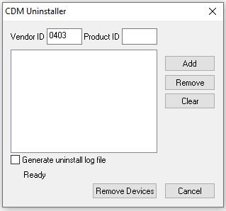
- Click Add and you should see a new item listed as below
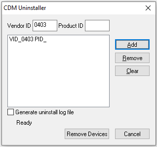
- Now click Remove Devices which will now uninstall all drivers for FTDI converters
- Once this is complete then restart Windows
- Download FTDI Drivers
- Unzip the folder and run the file labelled setup.exe
- Follow the install wizard to install drivers
- Once complete you can connect your USB Device and Windows will now install this using the correct drivers.
Active Boxes Expected Battery Life
Battery life for Loop Boxes, USB Timing Boxes, and Management Boxes varies based the loop power and the setup itself. Fully charged active timing boxes running firmware 2.6 (revision 39869) or newer firmware versions can achieve the following runtimes with a standard loop.
| Loop Power | Estimated Run Time |
| 20% | 25 hours |
| 30% | 25 hours |
| 40% | 24 hours |
| 50% | 23 hours |
| 60% | 22 hours |
|
70% |
20 hours |
| 80% | 18 hours |
| 90% | 15 hours |
| 100% | 12 hours |
Note: Energy consumption is highly dependent on your configuration. By optimizing the loop power setting, you can achieve more than double the operating time compared to always running at 100% power.