Chip2Go
Chip2Go allows you to program RACE RESULT raw transponders ready to stick directly to bibs.
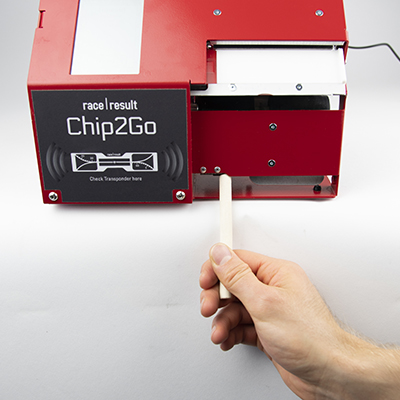
Raw transponders are fed in to the Chip2Go from a roll, encoded to the required number and fed out ready to easily remove and stick directly to a bib.
The unit features a chip check antenna on the front side to easily check a transponder's code.
Number entry can be achieved through either:
- Touchscreen keypad entry (with optional sequential count-up / count-down)
- USB number pad
- USB barcode scanner
The Chip2Go will only work with RACE RESULT raw transponders, these can be purchased in either single or duo configuration. The machine will automatically recognise these and will program either a single tags or two identical tags according to the roll.
System Setup
Screw in the power cable to the rear of the unit and the Chip2Go will power on automatically.
Chip2Go machines are shipped with a 15v power supply using the same connector as Loop Boxes and Track Boxes. Note that a Loop Box power supply only provides 12v, the Chip2Go will still run but motor speed will be reduced.
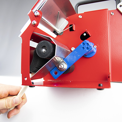
To prepare transponders first raise the mounting arm by pulling the black quick release latch and pulling the arm up until the latch clicks back in to lock the arm in place, the roll then fits on the arm.
Push back the silver brake plate and feed the plastic liner through the upper section of the unit until the first transponder is just visible below the red plate but ensure that the transponder does not cover the white programming antenna. If the programming antenna is already covered by a transponder then this transponder will be fed past the antenna and cannot be used.
On the display push Feed, or manual feed forward, and push the liner in to the slit below the programming antenna until the rollers catch the plastic liner and pull it through. The machine will keep feeding forward until the first transponder is positioned over the progamming antenna.
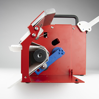
Once finished you can tear off the excess liner by using the serrated cutter on the lower slit, you should cut the liner here with a transponder still in place as the excess liner is required to feed in to the system at the next start-up.
On the display select Switch Mode and then press manual feed reverse to feed the liner back out of the lower section, if the liner was not cut then it may require multiple presses to fully remove.
The transponders can now be pulled out from the upper secction, the roll removed and the mounting arm returned to it's transport position. To power down the unit simply remove the power supply.
Transponder Number Entry
Chip2Go can encode any number from 1-9,999,999
Transponder Check Antenna
The check antenna on the front side of the Chip2Go can be used to check the chip code of any passive race result transponder.
Simply hold the transponder in front of the check antenna and the chip code will be displayed at the bottom of the display.
If 2 or more transponders of the same code are detected then "Number x 2" will be displayed.
If 2 or more transponders with different codes are detected then "multiple tags" will be displayed.
Firmware Update
The current version is always shown in the top left screen corner.
How to Update
When running firmware is 0.9.9 or newer, the stick with the update must be inserted prior to boot and the machine will ask you whether to update or not. After installing the update, your Chip2Go will reboot and ask you again whether to update or not. Unplug the USB drive now, then abort the message. You may be asked to install 2 further updates, which you can't abort. After installing these updates, your Chip2Go is updated and can be used again.
Note: there must not be more than one firmware file on the USB drive and the drive must be formatted as FAT32.
pre-0.9.9
Download the latest update below and copy this file to a USB drive. Connect the USB drive to the Chip2Go machine and after a short while the LED on the programming antenna will start to flash red and Green
Once the LED changes to just green remove the USB drive and the machine will reboot with the new firmware.
Note: there must not be more than one firmware file on the USB drive.
Changes
-
1.1.4 - Released June 19th, 2024
- show reader busy when tag antenna is inactive
- internal improvements
-
1.1.2
- Fix date encoding bug in order ID for programmed tags
-
1.0.5d
- Handle end of roll properly
- Selectable step width when selecting a USB file
- Barcodes to enable/disable menu (barcodes attached below)
- Fixed error with device licking up if a USB file is not selected
- Feeder timeout race condition fixed
- Improved feed error handling
- Fixed crashing issue
- Other minor improvements
-
1.0.4
- Readjusted check antenna limits after user feedback
-
1.0.2
- Not ready message (new number entered while old tag not picked up) is clearer
- Discard input when not ready for new input
- Improve handling of tag gaps and roll end in single tag mode
- Adjust check antenna power
- Minor improvements
-
1.0.0
- Massive improvement in non-EU and US tag programming reliability
- Race condition during programming could lead to a hanging machine, fixed.
- Pulling tags forward no longer freezes the machine
- Show programmed tag counter and icon for detected usb devices in status bar
- Handling of errors reworked
- USB file reading implemented
- Log file assistant after crashes
- Update of system and UHF firmware must be confirmed, progress is shown for UHF firmware
- Logging reworked, more errors get captured for analysis
- Internal: Log file retention age and size increased
- Further smaller fixes and improvements
-
0.9.5
- Country selection for regulatory compliance
- Improved programming speed and stability
Reinigungsanleitung
Die Gummiwalzen im Inneren der Chip2Go können sich im Laufe der Zeit mit Staub zusetzen, was auf Dauer zu Problemen führen kann. In diesem Fall können die Walzen einfach gereinigt werden. Hierfür legen wir jeder Chip2Go eine Bürste bei.
Stellen Sie dazu die Chip2Go z.B. an eine Tischkante und schalten Sie sie ein. Zum Reinigen darf keine Rolle mit Chips in der Maschine sein. Befeuchten Sie die Bürste leicht mit Wasser, oder im Falle von stark fettigen/öligen Verschmutzungen mit etwas Alkohol (z.B. Isopropanol). Die Bürste darf dabei nicht komplett getränkt sein, damit keine Flüssigkeit in die Maschine läuft.
Führen Sie die Bürste durch den unteren Schlitz ein, durch den sonst der leere Liner herauskommt. Wenn Sie die Bürste in den oberen Schlitz einführen besteht die Gefahr, dass sie im nächsten Schritt in die Maschine eingezogen und beschädigt wird.
Drücken Sie auf die Schaltfläche „feed“ sodass die Walzen sich drehen. Pressen Sie die Bürste auf die Rolle und schrubben sie leicht nach links und rechts. Wiederholen Sie dies je nach Stärke der Verschmutzung und spülen nach jedem Durchgang die Bürste aus.
Sie müssen die Maschinen nicht aufschrauben, dies dient hier nur zur Illustration.
Sie können nach der Reinigung ein Papiertuch/Küchenrolle o.ä. auf die Breite des Liners falten und einige Male durch die Maschine fahren lassen, um die Walzen abzutrocknen. Halten Sie das Tuch auf keinen Fall fest, da es dadurch abreißen und im Inneren der Maschine für Störungen sorgen könnte.
RACE RESULT SIM-Karte [EU, US, CAN]
RACE RESULT SIM-Karten sind ausschließlich für den Gebrauch in RACE RESULT Equipment bestimmt, d.h. für das RACE RESULT System sowie Track Boxen.
Die RACE RESULT Hardware setzt automatisch alle Einstellungen, so dass Sie keine weiteren Änderungen vornehmen müssen.
Unterstütze Firmware
- Firmware Version 2.25 oder höher ist benötigt für das race|result System.
- Track Boxen benötigen Firmware revision 20938 oder höher (Sie müssen für das Update Ihre eigene SIM-Karte verwenden).
Wenn Sie eine ältere Firmware verwenden, werden die Karten gesperrt und müssen kostenpflichtig entsperrt werden (siehe Vertrag).
Die SIM-Karten funktionieren weltweit, sind allerdings ausschließlich in den folgenden Ländern ohne Aufpreis nutzbar (Vorsicht: Dänemark ist nicht inkludiert)
Bitte lesen Sie den Vertrag sorgfältig!
EU & Nordic
- Österreich
- Belgien
- Bulgarien
- Kroatien
- Zypern
- Tschechische Republik
- Estland
- Finnland
- Frankreich (inkl. Guyana, Guadeloupe und Martinique)
- Deutschland
- Gibraltar
- Großbritannien
- Griechenland
- Niederlande
- Ungarn
- Island
- Irland
- Italien
- Lettland
- Litauen
- Luxemburg
- Malta
- Montenegro
- Norwegen
- Polen
- Portugal (inkl. Azoren und Madeira)
- Réunion
- Rumänien
- Serbien
- Slovakei
- Slowenien
- Spanien (inkl. Kanarische Inseln)
- Schweden
- Schweiz
Nordamerika
- USA
- Kanada
BLE Reader
The RACE RESULT BLE Reader connects to the RACE RESULT EventTools App, it reads RACE RESULT Passive Transponders. The reader is not designed or optimized to be used as a timing device.
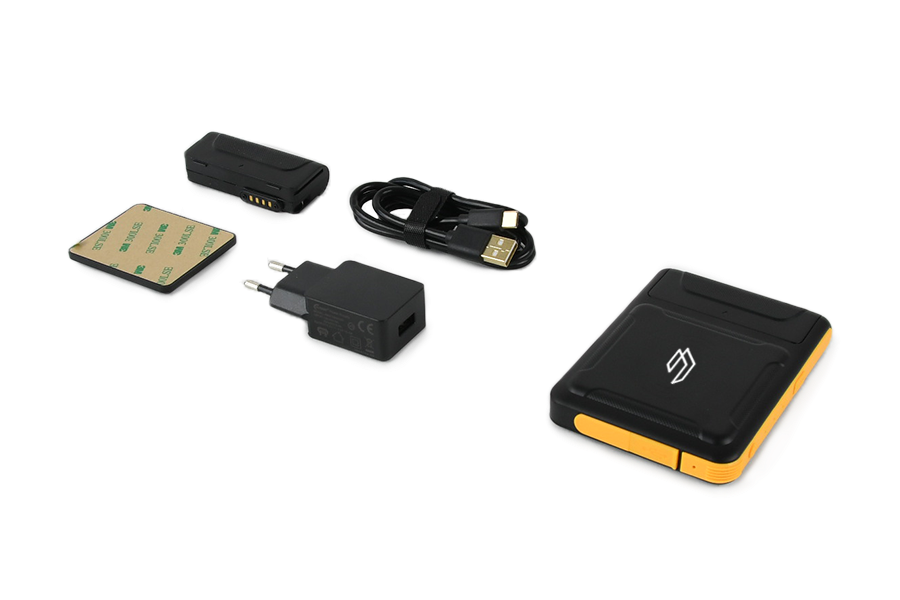
The package includes:
- RACE RESULT BLE Reader
- Spare Battery
- Stick-on magnetic pad
- 5V USB Charger
- USB-A <-> USB-C charging cable.
The battery can be slid out to exchange, if the reader is turned on when the battery is removed it will automatically switch back on when a new battery is fitted.
Buttons & LEDs
The reader has 2 buttons, and 3 LEDs along the top edge.

Buttons
Press and hold the small round power button to switch the device on or off.
At this time the button labelled scan is not used for any operation.
LEDs
Power
- Solid Red - Device is charging
- Solid Green - Battery level above 20%
- Blue - Battery level below 20%
- Off - device is switched off
Bluetooth
- Blue - Bluetooth is connected
- Off - No bluetooth connection
Work
- Flashing Blue - Reading transponders
Technical Specifications
Dimensions & Standards |
|
|---|---|
|
Regulatory Conformity and Standards |
EN60950 (safety) CE, RoHS, FCC |
| Operating Temperature | -20°C to 60°C |
| Dimensions | 108mm x 78mm x 18mm |
| Weight | 200g / 7.05oz |
|
Protection Class |
IP65 -dust tight- |
| Drop Resistance | 1.2m |
Battery |
|
| Capacity | 2000mAh |
| Battery Life |
IDLE - 17h @5dBm - 5h30 @10dBm - 5h15 @15dBm - 5h00 @20dBm - 4h45 @30dBm - 3h00 |
UHF |
|
| Power Output | Adjustable 5dBm - 30dBm |
| Antenna |
Circular Polarized 3dBi |
| Frequency | 865-868MHz / 902-928MHz |
| Expected Read Range |
@5dBm - 0.3m @10dBm - 0.5m @15dBm - 1m @20dBm - 2.5m @30dBm - 6.5m |
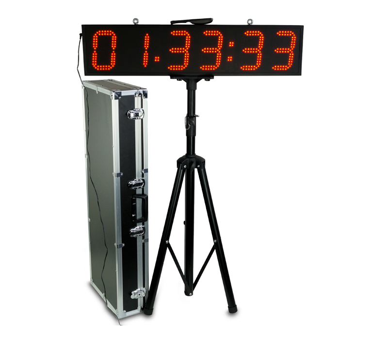
LED Clock
Here you will find documentation about the clock we started selling in early 2018. For the previous model, read the instructions for the LED Clock (old).
The current version of the clock has been further improved in November 2018, with the following improvements and modifications:
- 3.5 mm jack input for start / stop impulses added
- Easier selection and automatic switching between time formats.
- Countdown allows unlimited repetition
- Improved accuracy in all modes
- Unnecessary modes removed.
This manual details the functions of the latest version, with notes for the former version where functions differ. If you have purchased your clock before November 2018 and it does not have a 3.5 mm jack output on the side, you will need to refer to these notes.
The quick start guide gathers all the necessary information for simple use. Read further if you want to find out about the more advanced features of the clock.
Quick Start Guide
1. Set up the clock on the tripod using the thumbscrews and plug in the power supply.
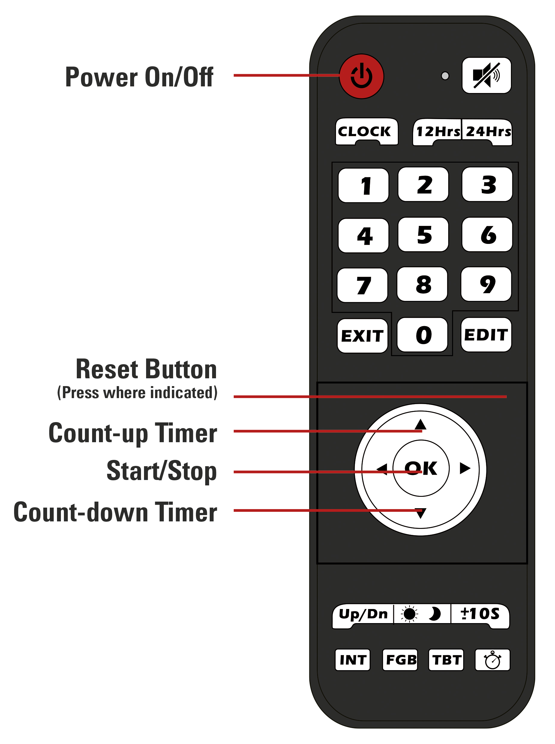
2. Press the red On/Off button of the remote to turn on the clock.
3. Press the Up or the Down Arrow to enter the count up or count down mode.
a) If you want to start with a preset time, press the "Edit" button.
b) Use the number pad to enter the desired time.
c) press "Edit" again to save the time.
4. Press "OK" to start the timer.
5. Press "OK" again to pause the timer.
6. Press the reset button (not labeled) to reset to the preset time.
Remote and Modes
Note: the remote and modes have been modified in November 2018. If you have purchased your clock before then and it does not have a 3.5 mm jack input on the side, please refer to the sub-section for your version below.
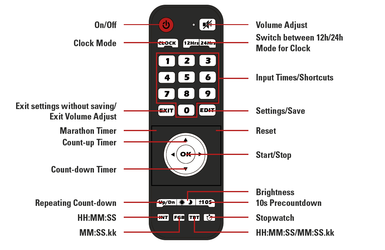
Remote:
Display Format
During setup the clock always uses the HH:MM:SS format.
For the Count-up and Count-down mode the desired display format can be chosen with the INT, FGB and TBT buttons.
- INT: HH:MM:SS (max 99:59:59)
- FGB: MM:SS.kk (max 99:59.99)
- TBT: automatically switches between the two modes when 1 hour is reached
Input Jack
A 3.5 mm jack input is accessible on the side of the clock, under the connector for the power supply.
This input can be used to collect impulses from any kind of device to start and stop the clock, just as if you were pressing the OK button.
Modes:
Countdown / -up
Function: count down from or up to a specified time
Time format: HH:MM:SS
Accuracy: ±140 ppm
To access and use countdown / - up:
- Press the "Up" button to count up, or the “Down” button to count down
- Use the “Edit” button to set the time to count up or down from
- Enter the desired time using the number pad
- Press “Edit” again to save
- Use the “±10S” button to turn the 10 second pre-countdown on or off
- “-10” stands for no pre-countdown
- “10” stands for 10 second pre-countdown
- Select desired display format using the INT, FGB, or TBT button
- Press “OK” to start/pause the timer
Clock
Function: displays a normal clock in either 12h or 24h format
Time format: HH:MM:SS
Accuracy: ±20 ppm
To access and use the Clock mode:
- Press the “Clock” button
- Use the “12Hrs” and “24Hrs” buttons to switch between 12 and 24-hour format
- Use the “Edit” button to set the clock
- the first digit will start flashing and can be set using the number pad
- when done setting the time press “Edit” again to save the time
Stopwatch
Function: stopwatch
Maximum time: 99:59.99
Time format: MM:SS.kk
Accuracy: ±20 ppm
To access and use the stopwatch:
- Press the stopwatch button to enter Stopwatch mode
- Use the “±10S” button to turn the 10 second pre-countdown on or off
- “-10” stands for no pre-countdown
- “10” stands for 10 second pre-countdown
- Press “OK” to start/pause the stopwatch
- Use the reset (not labeled) button to reset the stopwatch when it is paused
Marathon Timer
Function: stopwatch with internal backup (the time continues to run even if the clock is unplugged)
Time format: HH:MM:SS
Accuracy: ±20 ppm
To access and use the Marathon Timer:
- Press the marathon timer button (not labeled)
- Use the “±10S” button to turn the 10 second pre-countdown on or off
- “-10” stands for no pre-countdown
- “10” stands for 10 second pre-countdown
- Press “OK” to start/pause the stopwatch
- Use the reset (not labeled) button to reset the stopwatch when it is paused
Repeated Countdown
Function: repeats the set count-down timer
Time format: HH:MM:SS
Maximum time: 99:59:59
Accuracy: ±20 ppm
To access and use the Interval Timer:
- Press the “Up/Dn” button to enter interval mode
- Press the “Edit” button
- Enter the desired time using the number pad
- Press “Edit” again to save
- Use the “±10S” button to turn the 10 second pre-countdown on or off
- “-10” stands for no pre-countdown
- “10” stands for 10 second pre-countdown
- Press “OK” to start/pause the timer
Technical specifications
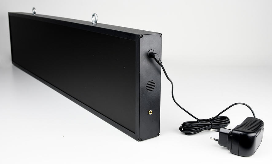
Weatherproof
Input 12V, 2A 
Clock: 88 x 20 x 5 cm; 3,2kg
Case: 101 x 39 x 17,5 cm
Power supply
Plug in the LED clock using the included 12V power supply or equivalent. The power supply comes with an adapter for different countries.
5,5mm Barrel connector
You can also use a 12V car battery with and adapter.
The remote uses 2 AAA batteries
Tag Reader
Der Tag Reader liest alle race|result Passiv-Transponder und wird für folgende Zwecke eingesetzt:
- Chip-Kontrolle an der Startunterlagenausgabe
- Chip-Zuordnung an der Startunterlagenausgabe
- Erstellen von Chip Files
- Urkunden-Terminals
Der Tag Reader kann nicht für die Zeitnahme verwendet werden!
Um den Tag Reader zu verwenden, öffnen Sie das TagTool. Das TagTool emuliert eine Tastatur, wenn ein Transponder gelesen wird, wodurch die Transponder ID in das aktuelle Feld geschrieben wird.

LED Großanzeige (alt)
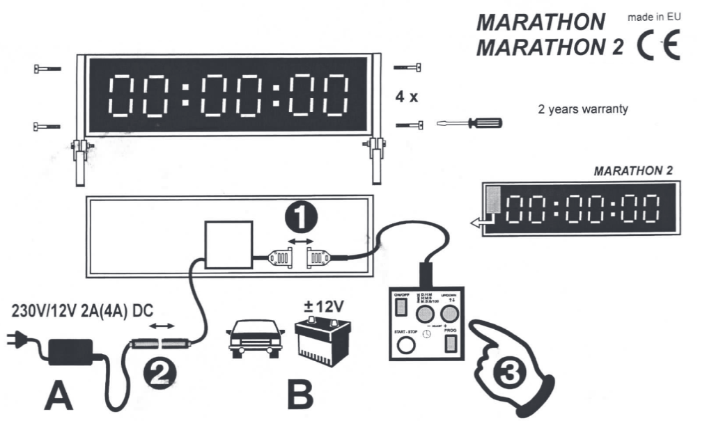
- Verbinden Sie die Fernbedienung wie auf der Abbildung oben
- Verbinden Sie die Stromversorgung wie auf der Abbildung oben. Es gibt zwei Möglichkeiten die Großanzeige (GAZ) mit Strom zu versorgen; entweder über das beiliegende Netzteil oder mithilfe der beiden Krokodilklemmen und einer 12V Autobatterie bzw. einer anderen 12V Spannungsversorgung.
- Schalten Sie die GAZ mit dem 'ON/OFF' Knopf an und warten Sie bis das Folgende angezeigt wird: H┌┐:--:--
Es gibt zwei grundlegen Möglichkeiten die GAZ zu betreiben; hoch oder runter Zählen. Für beide Möglichkeiten kann man die zeitliche Auflösung (im Folgenden 'range' genannt) sowie die Start-Zeit einstellen.
Das Zeichen an erster Stelle gibt Aussage über die 'range', das zweite Zeichen ob die GAZ hoch oder runter zählt. Die 'range' kann mit dem 'RANGE' Knopf eingestellt werden. Über den 'UP/DOWN' Knopf kann die Zählrichtung eingestellt werden. ' ┌┐ ' als zweites Zeichen, zeigt an, dass die GAZ nach oben zählt und ' ⌴ ', dass sie nach unten zählt. - Range:
Modus
GAZ; erstes Zeichen
Bedeutung
D:H:M
d Tag Tag : Stunde Stunde : Minute Minute
H:M:S
H Stunde Stunde : Minute Minute : Sekunde Sekunde
M:S:S/100
n Minute Minute : Sekunde Sekunde : 1/10 1/100
- Um das Setup zu verlassen und in den 'Uhr-Modus' zu kommen betätigen Sie den 'PROG' Knopf.
- Falls Sie eine andere Start-Zeit als 00:00:00 auswählen wollen, betätigen Sie den 'PROG' Knopf erneut.
Die erste Ziffer beginnt nun zu blinken und lässt sich mit den '+' und '-' Knöpfen einstellen. Durch erneutes Betätigen des 'PROG' Knopfes können Sie die nächste Ziffer auswählen. - Wenn die gewünscht Start-Zeit gewählt wurde, können Sie die GAZ mit dem 'START-STOP' Knopf starten.
- Um die GAZ wieder auf die vorher eingestellte Start-Zeit zurück zu setzen, drücken Sie den '+' und '-' Knopf gleichzeitig.